This site is best viewed at 1024 x 768
|
Wireless Set No.19 High Power RF Amplifier
|
||
 |
||
|
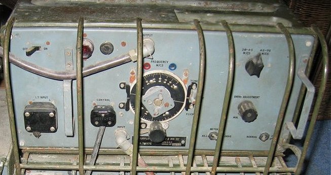
Front view of the controls of the Wireless Set No.19
High Power RF Amplifier.
|
||
 |
||
|
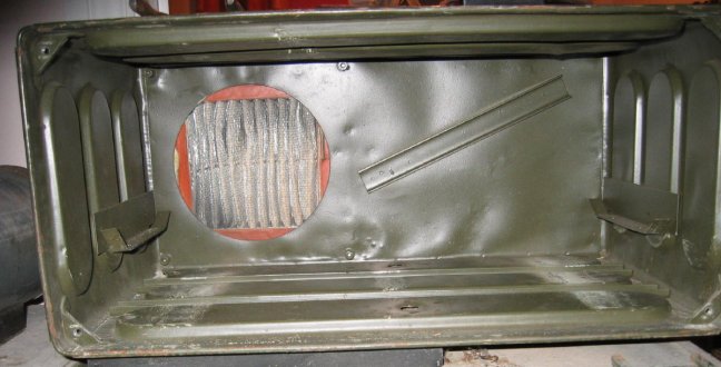
Inside view of the amplifier case, you can see the
air vent for the large dynamotor at the back left side of the case,
this is where the fan on the dynamotor sucks air through to cool the
amplifier and motor.
|
||
 |
||
|
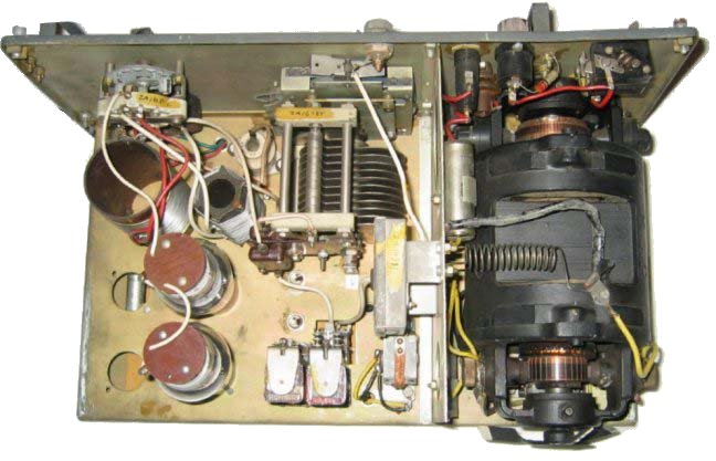
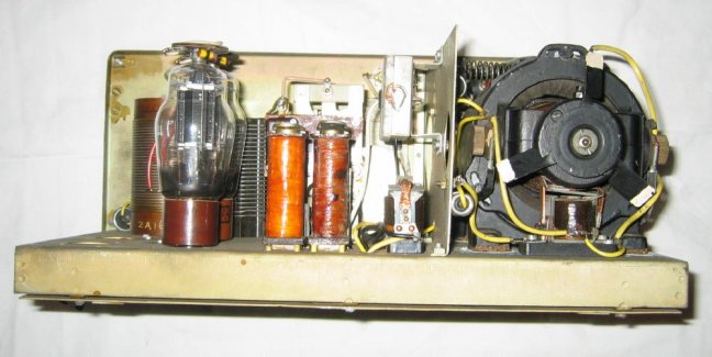
Top side view of the amplifier showing the pair of
807 PA valves (tubes) on the left and the large dynamotor power supply
on the right, power and RF switching relays in the middle at the bottom
of the photo.
|
||
 |
||
|
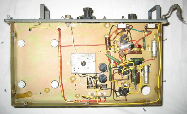
Inside bottom view with screening cover removed, the
silver square box in the middle of the chassis is the input RF transformer
that sends a DC voltage back to the WS19 to indicate low power RF output
when the HP Amp is switched off.
|
||
 |
||
|
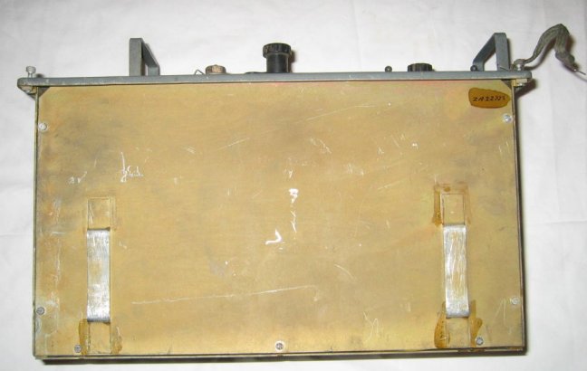
Bottom view of the amplifier with the screening plate
in place.
|
||
|
|
 |
|
|
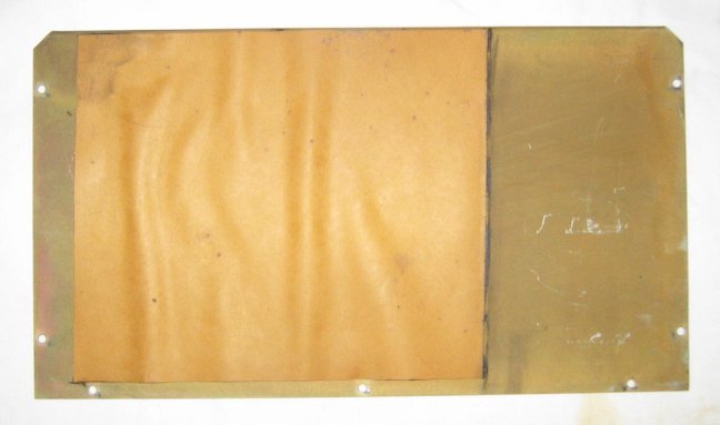
Under side of the screening plate showing the insulator
surface.
|
||
 |
||
|
Rear view of the amplifier showing the fan on the
back of the dynamotor for cooling, also a clear view of the two 807
Pentode valves (tubes) and the RF/DC switching relays. You can also
make out the RF transformer used to indicate high power RF output when
the amplifier is in use, by sending a DC voltage back to the WS19, this
can be seen on the vertical screening plate, left side top of the screening
plate.
|