GuusNL11047 - Restoration of an R209 Mk2/B
I was looking for a valve receiver with some work to learn more about restoration issues and IF/RF alignment. By coincidence I came across an advert for an R209/2/B, which would be a nice project after finishing the repair of several Telefunken R77 receivers (interesting small hybrid valved/solid state radio from the ‘60s, could be another article. The R209 Mk2/B came with two IF units, still sealed in their 1969 packaging, 4 spare valves and documentation (copies). The pictures showed a set “improved” by a previous owner. Handles were attached on the sides, it was painted over in black and silver, a direct feed made into the front for the mains cable, 6.3 mm phone socket, etc. The seller didn't want to sell just the two IF units and valves which had my attention. It was offered for the total of 45 Euro (38 GBP). I decided to give it a try and see if I could restore it to original condition and compare it to the Dutch Army R209 Mk2/B, which I have for about 40 years. An initial test revealed that it was in working condition. With just a finger on the AE input, stations could be heard in AM and SSB. The project was obviously more on the outside than the inside. |
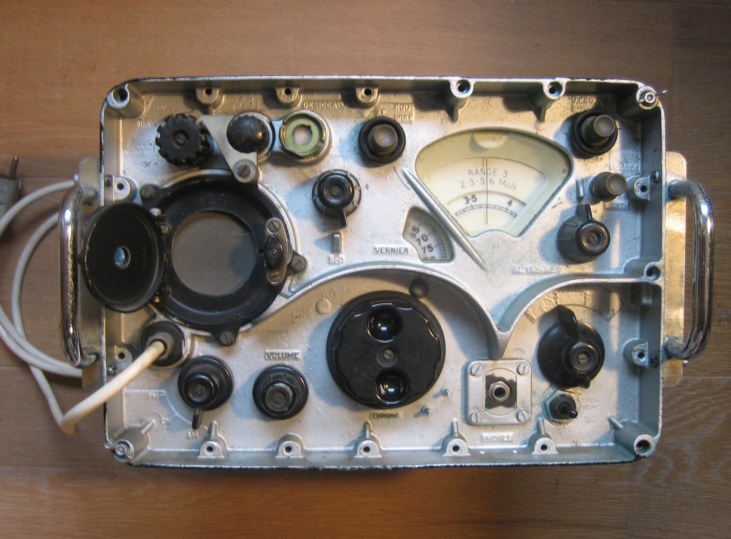
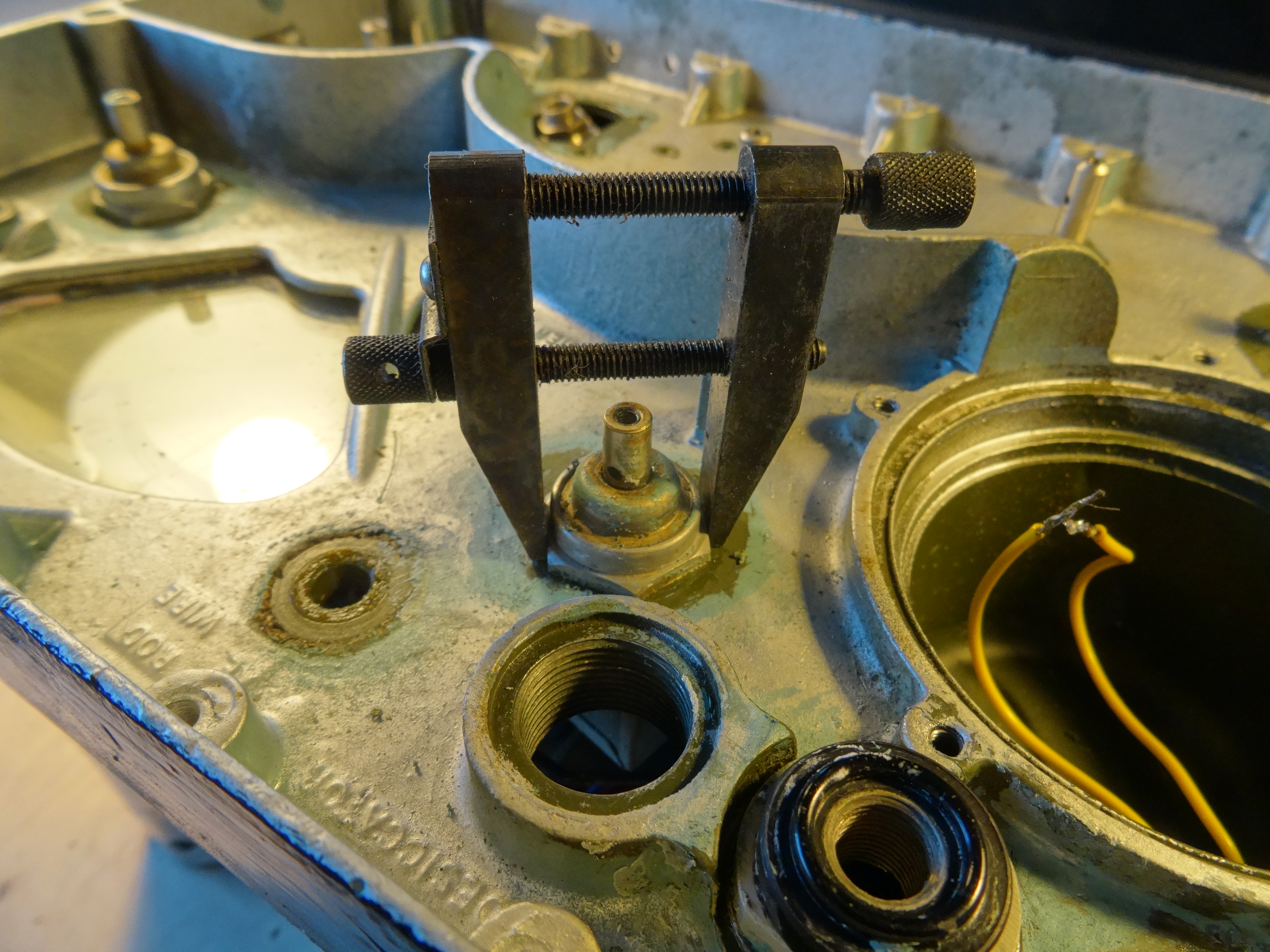
| It would require the removal of the non-original parts, removal of the paint, re-spray and a search for original parts. Especially the missing Plessey Mk4 size 1 mains socket is disturbing. With help of Keith G4MSF, the order of dismantling steps was clear and I obtained the correct colour code: BS 381c colour 298. The paint on the case was easy to remove and the original could serve as primer for a fresh layer. Spray cans with all kinds of army greens are available, but not exactly this type. It could be custom made though, as the colour code was listed in the software of the mixing machine. A test showed the right colour, it matched perfectly with untouched inside surfaces. Due to age and extra layers of paint, the hex-nuts with seals were difficult to remove. A spanner is not practical, there is not enough room to get it in the right position. I solved this by clamping the hex-nut very tight with a parallel steel clamp. A drop of penetrating oil and ample time, softens the old grease and grime. The fuse holder could not be removed, whatever force was applied. Probably due to the lead-seal washer used. |
| Once all the leads are disconnected, knobs, seals and screws removed the radio's chassis can be taken from the front panel. The 4BA screws holding the front to the receiver main parts were not very tight. One would expect that this requires either serrated washers or some other form of thread-locking to withstand vibration. There is no need to dismantle the different sections of the chassis, just take the chassis out all in one piece. To prevent damage to the middle section with V9 and V10 on the pertinax board, keep the securing clamp holding the 3 IF and DISC sections in place. Add a nut on one end to secure it at both ends. The silver paint could then be removed from the front panel with paint stripper. Repainting over the old paint was not an option, it was unsightly. The alternative would be to have it blasted with glass beads (shot blasted). To me, that could be risky since details in the lettering could get lost if the blasting is too aggressive. Eventually, with the help of tooth picks, old brushes and cotton swabs, all paint was removed. |
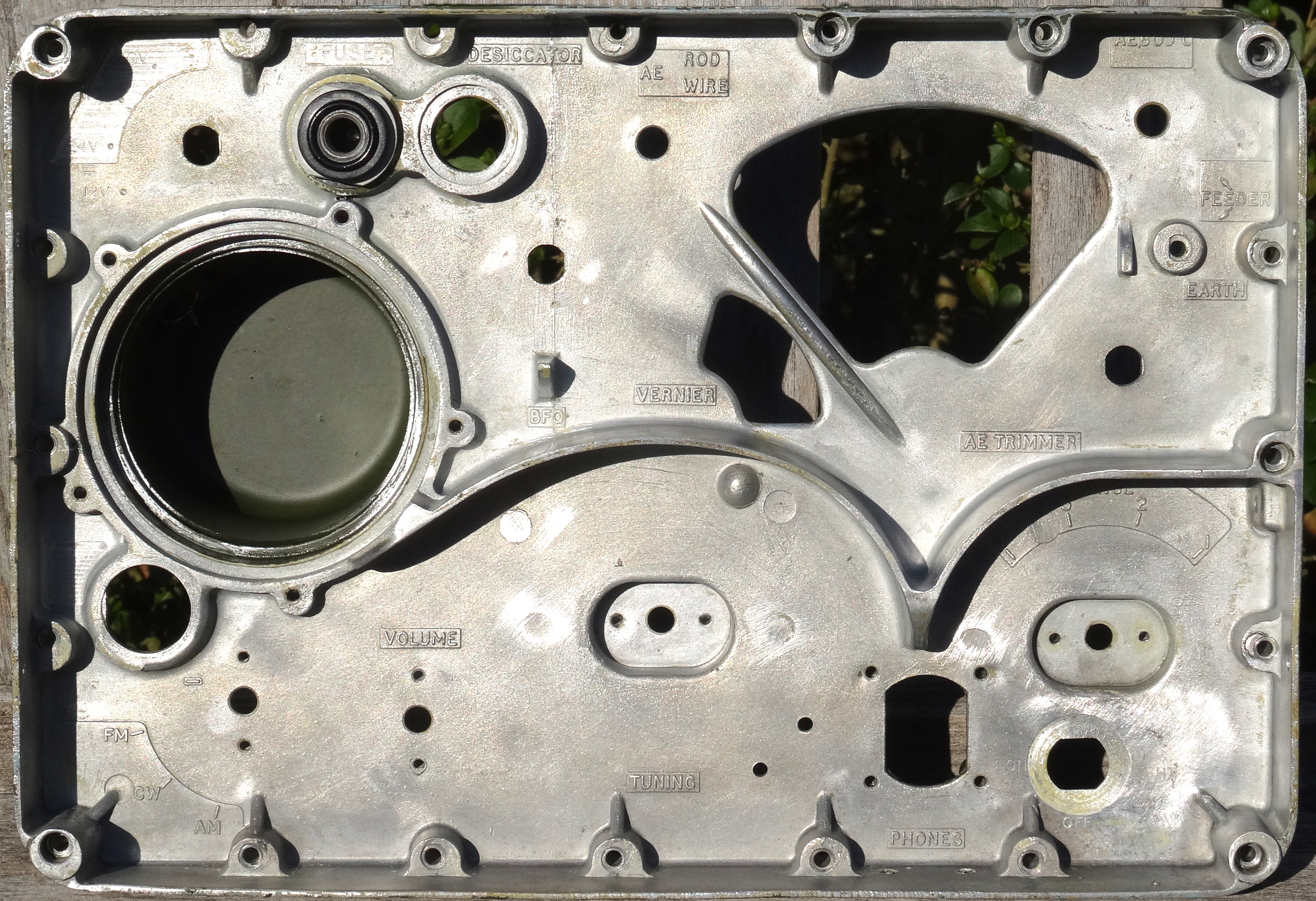
This was a quite a time consuming task. After cleaning the letter detailing comes out nicely.
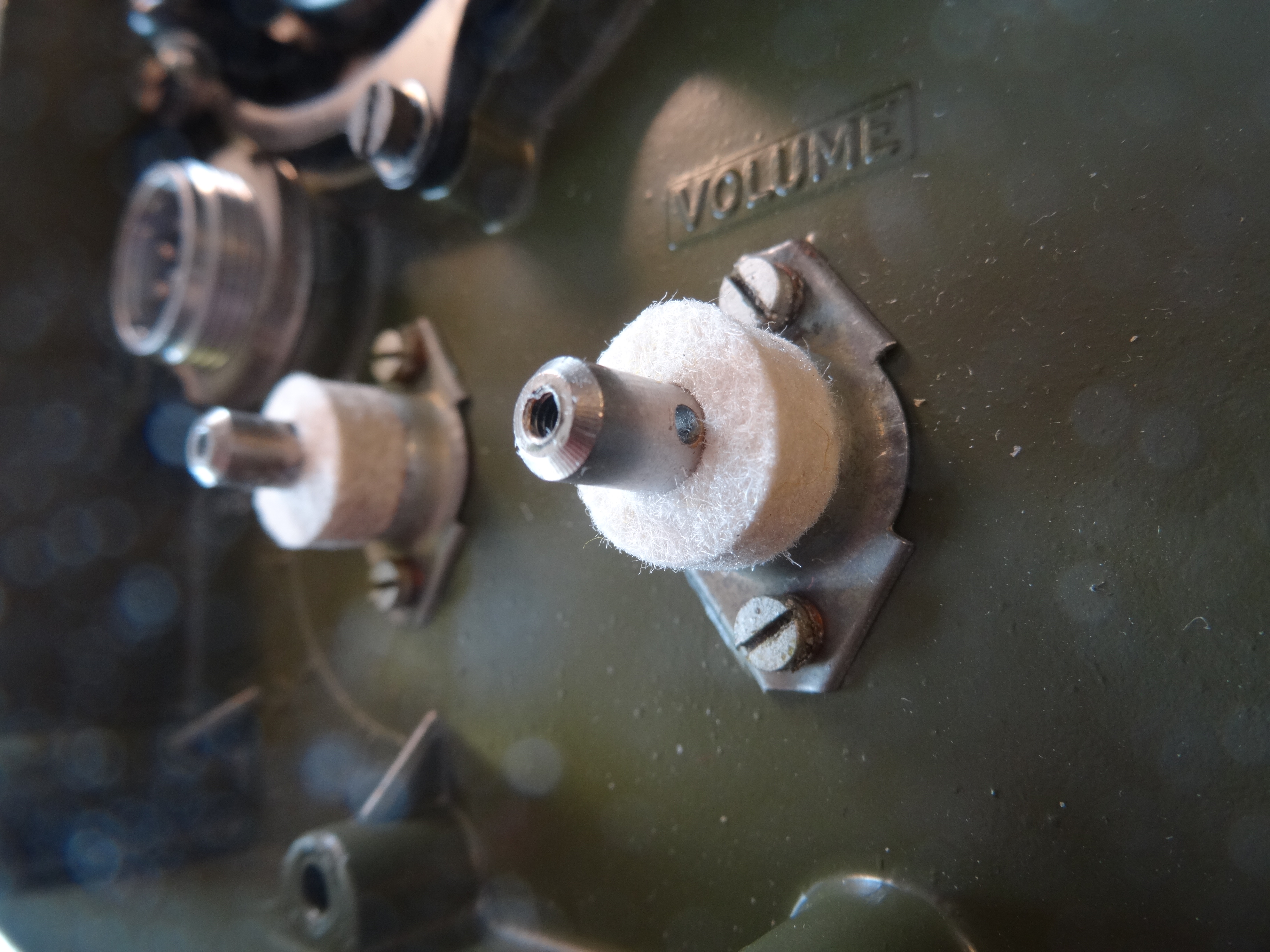
| During cleaning to get rid of remains of the old paint and stripper residue, I noticed that some screw holes were not as deep as others. They still contained the tiny chips from thread making, these were removed with pipe-cleaners. The rubber seals from the speaker, front-to-case and glass windows were cleaned with warm water and detergent. After drying, treated with talcum powder. It was quite remarkable how good of a condition they were in. Upon dismantling, I noticed that not only the mains-power socket was missing, but also the dial-lock. The studs for the dial-lock were still in place with no damage to the 6BA threads. The shafts of the switches and potentiometers are not only water-proofed with the rubber seals (2 different types) but also protected from dust with felt rings. A few were in the original position, but very dirty. I could get hold of technical quality felt, ¼” thickness. With sharp punches new rings could be made. Knobs were well cleaned, but not re-painted in order to maintain originality. |
| To attach the non-original handles, holes had been drilled in the left and right rims of the front panel by a previous owner. These could be filled with epoxy filler and sanded flat with waterproof abrasive paper. The paint-shop advised to use a dark primer before colour spraying. A dark red automotive primer was used. After degreasing the front panel, areas were masked using masking tape and small wooden pegs for the screw holes, a layer of primer was then applied. The deeper spots on the panel have to be sprayed from different angles. |
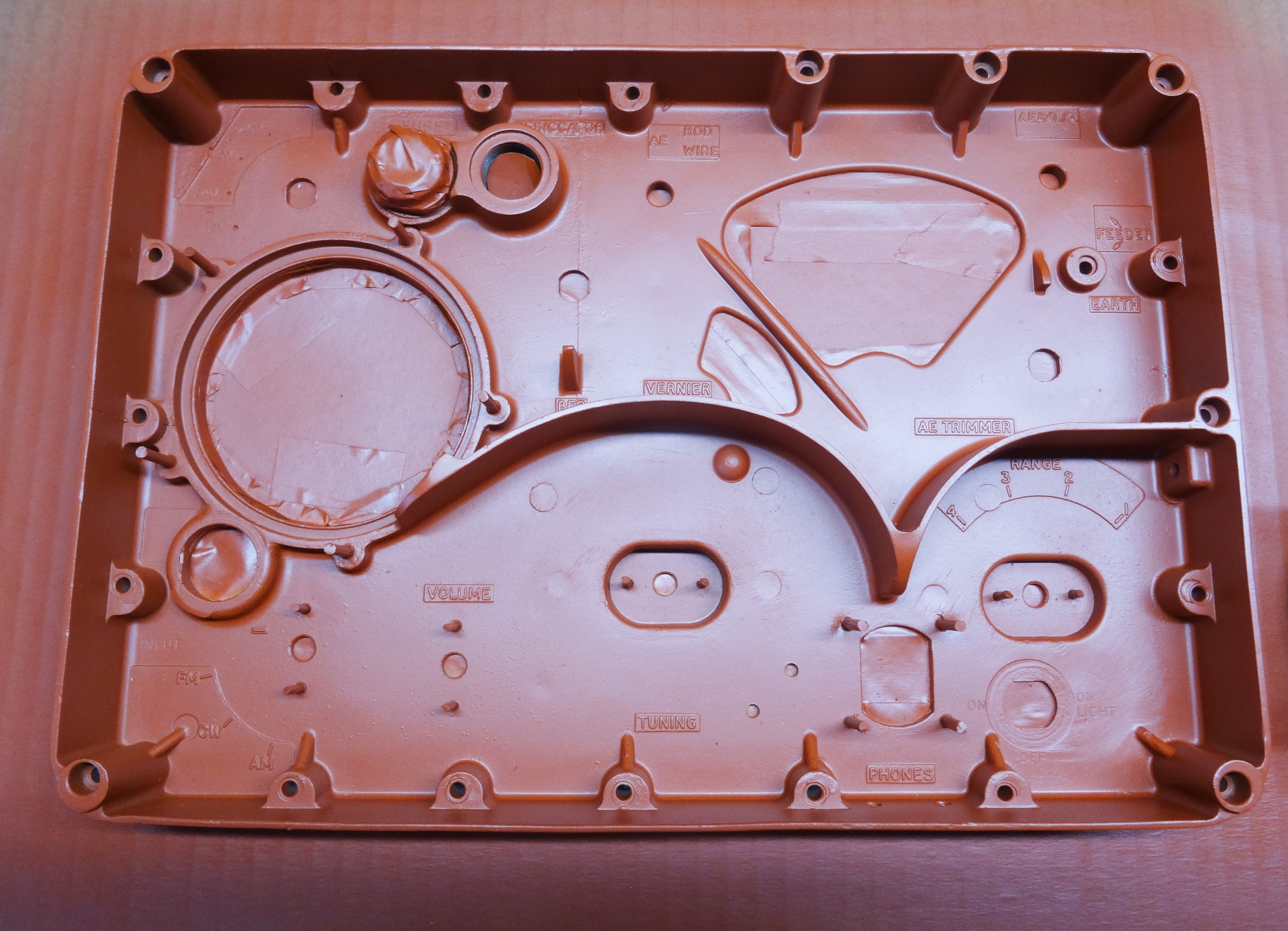
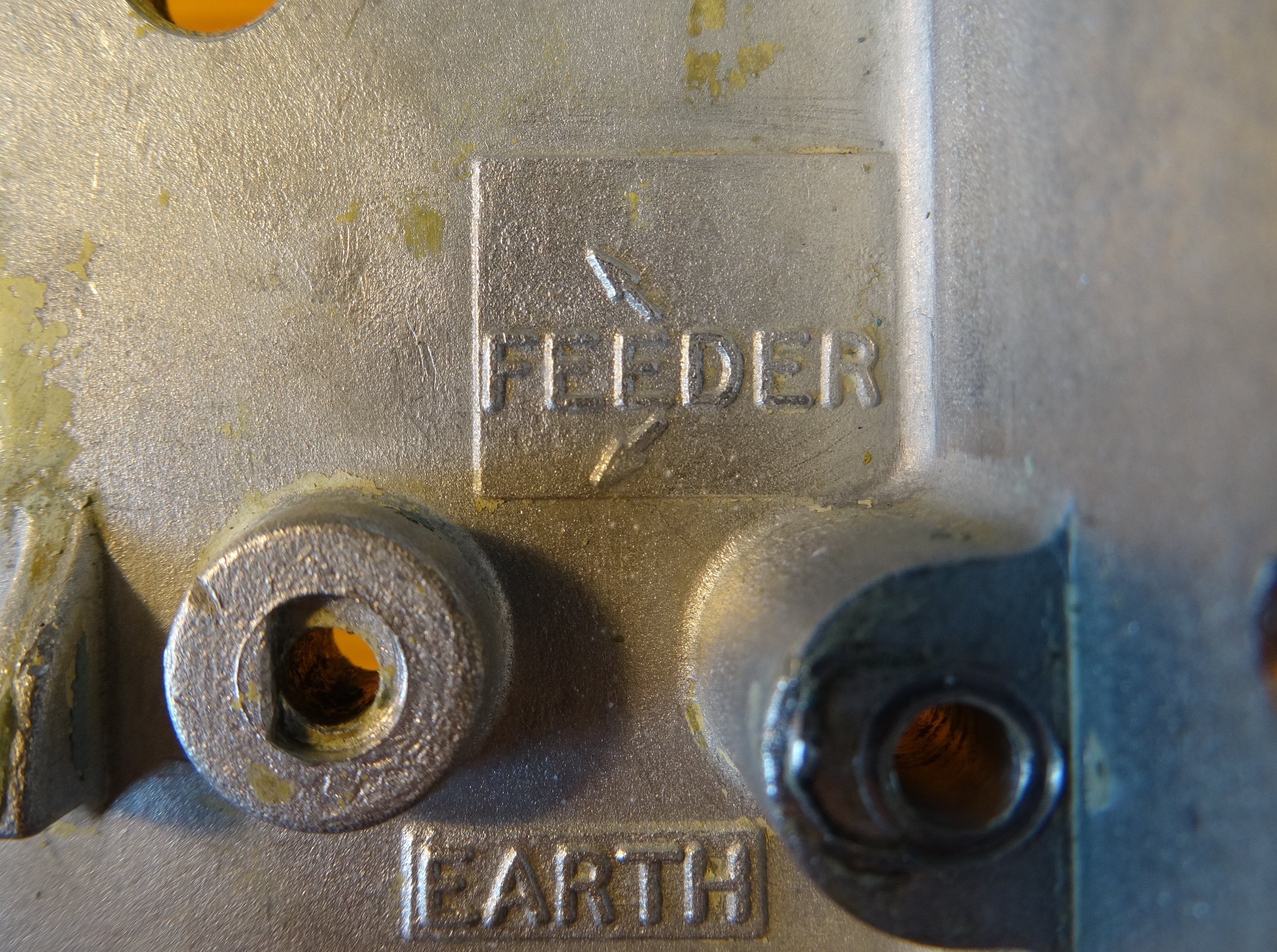
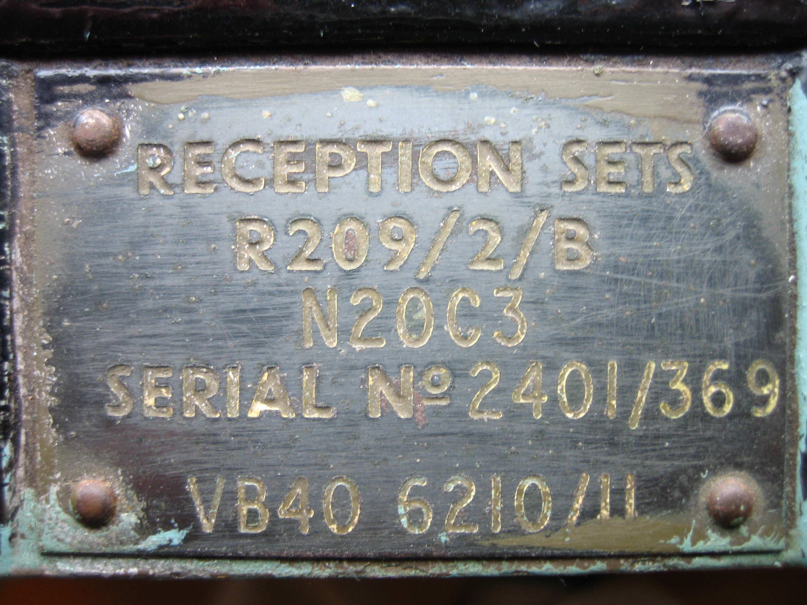
Once painted in the correct olive drab, the engraved markings and type plate could be re-filled with off-white alkyd paint with a special pen for stencil-lettering. It requires some experimenting to get the right viscosity of the paint by adding mineral spirits. This R209/2/B is probably from the UK and not Dutch, given the identification and serial numbers. |
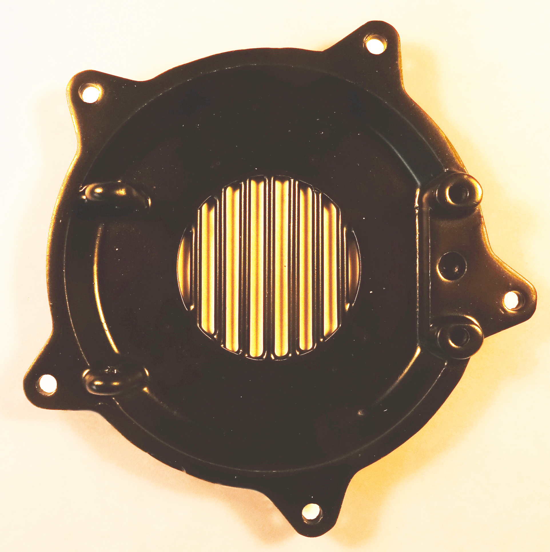
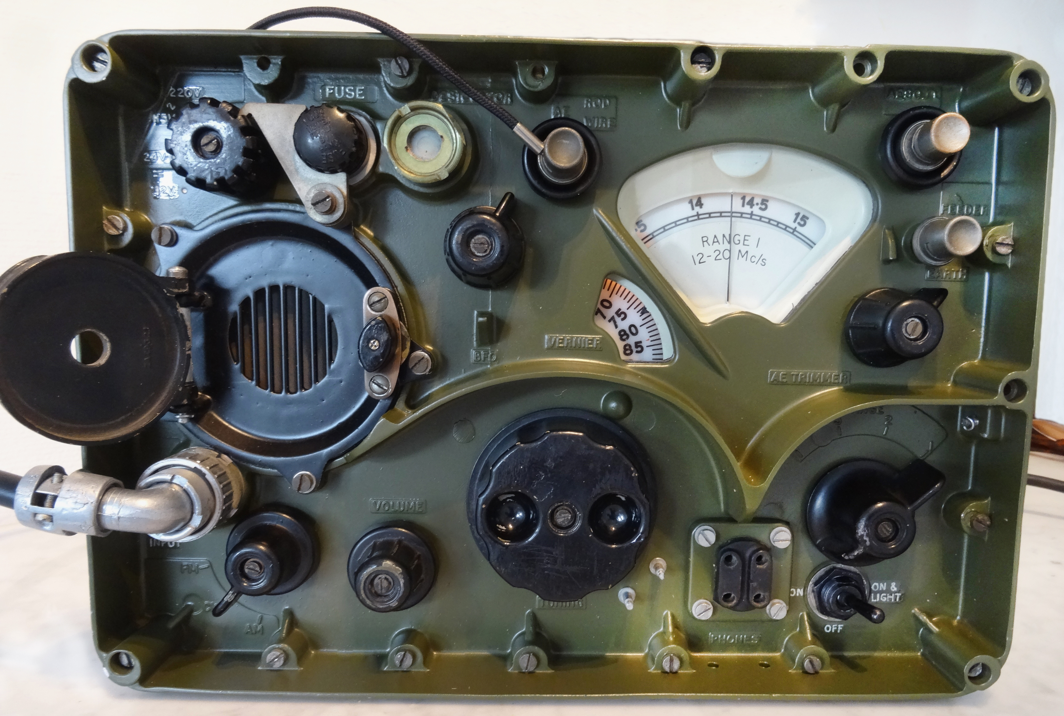
| The speaker grill and door assembly was “improved” by removing the small grill in the middle (see the first photo). Probably to get a better sound. The new, somewhat larger hole was not centered in the middle. I created an identical small grill from brass, equally thick as the surrounding material (2.3 mm), taken dimensions from the original on my other R209/2/B. This could be positioned exactly in the middle of the frame, with the slots parallel to the hinge axes and fixed with tape before applying epoxy filler. After cleaning up, sanding and matt spray paint, it is nearly identical. The part still missing is the flexible metal part with the rubber seal on the inside of the door. I have not figured out how this part is attached to the small door. |
| Since the radio itself was out of the case and with no front, cleaning and re-greasing of metal on metal moving parts could be done. I use Nyogel 744 synthetic instrument grease for that purpose. The non-metal gear wheals were cleaned, but not greased, including a tiny bit on the ball-bearing of the 3-gang tuning capacitor. I also took some time to touch up some of the markings and numbers on the Vernier scale. The desiccator element is original, but the indicator turned pink. The moisture detection is based on Cobalt-chloride paper (arrow) which turns from blue to pink if moisture is present once the desiccator gets saturated. The paper is placed behind a blue painted ring as reference. If you leave the indicator overnight on a hot central heating radiator it turns blue again. I have not figured out yet what type of desiccator is used, the chemical dictates if and how it can be regenerated. Spare desiccators were available in sealed aluminum containers with the warning “Not to be opened until required for us” on the screw lid. |
| The missing 4-way audio-connector and mains Plessey socket were kindly donated (Keith G4MSF and PA3ESA) to make the receiver complete. To take Plessey plugs and sockets apart for cleaning (removal of resin flux), later on proper fitting on the front and the connector on the mains cable, I use special tools. One is to fix the insert with the contacts in the plug or socket body (home-made), the other to tighten the ring of the angled cable outlet (home-made) and an adjustable spanner to tighten the front ring on the socket. New wires in the right color were soldered on before fitting in the front. The other R209/2/B serves as reference to sort out connections and wire colours since the circuit diagram does not mention AWG size/colour. |
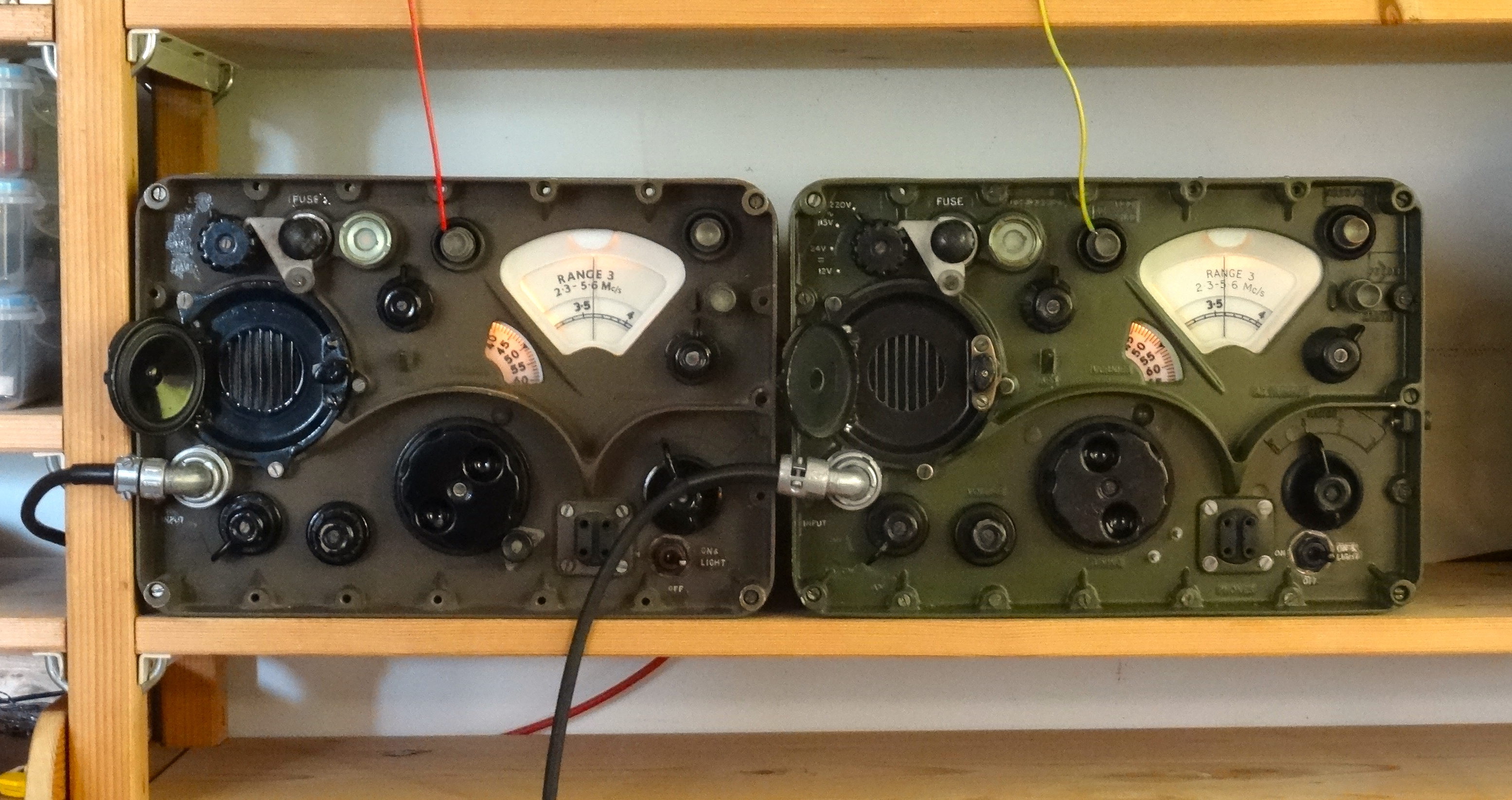
Since the mains voltage is now above 220 VAC, the input tab on the transformer was set to 230 VAC. Time to test the set on mains power supply and on 24 VDC. All bands were OK and stations on 40 and 80 meters were clear. I seldom use the other R209 on DC-supply, so I forgot about the hum of the vibrator, not recommended. The key voltages as given in EMER E 314/1, while on mains supply, were in about the proper range. Visual inspection for leaky capacitors or other faulty parts didn't reveal anything special, surprisingly. What I still could do is to test the overall smoothing of the LT and HT voltages. If that is not OK, a second look at capacitors could be required, though I have not a good view on how to tackle this without dismantling. The overall result turned out very satisfactory to me and compares very well to the Dutch Army R209/2/B (on the left of the last photo below). With seals, switches and gears cleaned and re-greased it operates smooth, very tempting to overhaul some parts in the other set as well. With a dial-lock, a few 6BA nuts, 4BA 1¼ plus 1¾ cheese-head bolts, and the part of the speaker door with the rubber seal, will make the R209 Mk2/B complete, but are not critical. |
GuusNL11047
![]()
Click here to subscribe to The Wireless-Set-No19 Group.
Site and all files are copyright © 2004 - 2024 Keith Watt RN (Rtd.).