This site is best viewed at 1024 x 768
Please email at to have your photos added.
|
An unusual HT inverter for surplus
equipment, by Jan, PA0CHS.
Almost 10 years ago this inverter was published in the Dutch SRS
surplus magazine. It was designed by Philips and intended for use
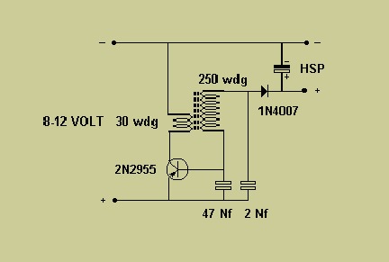
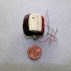
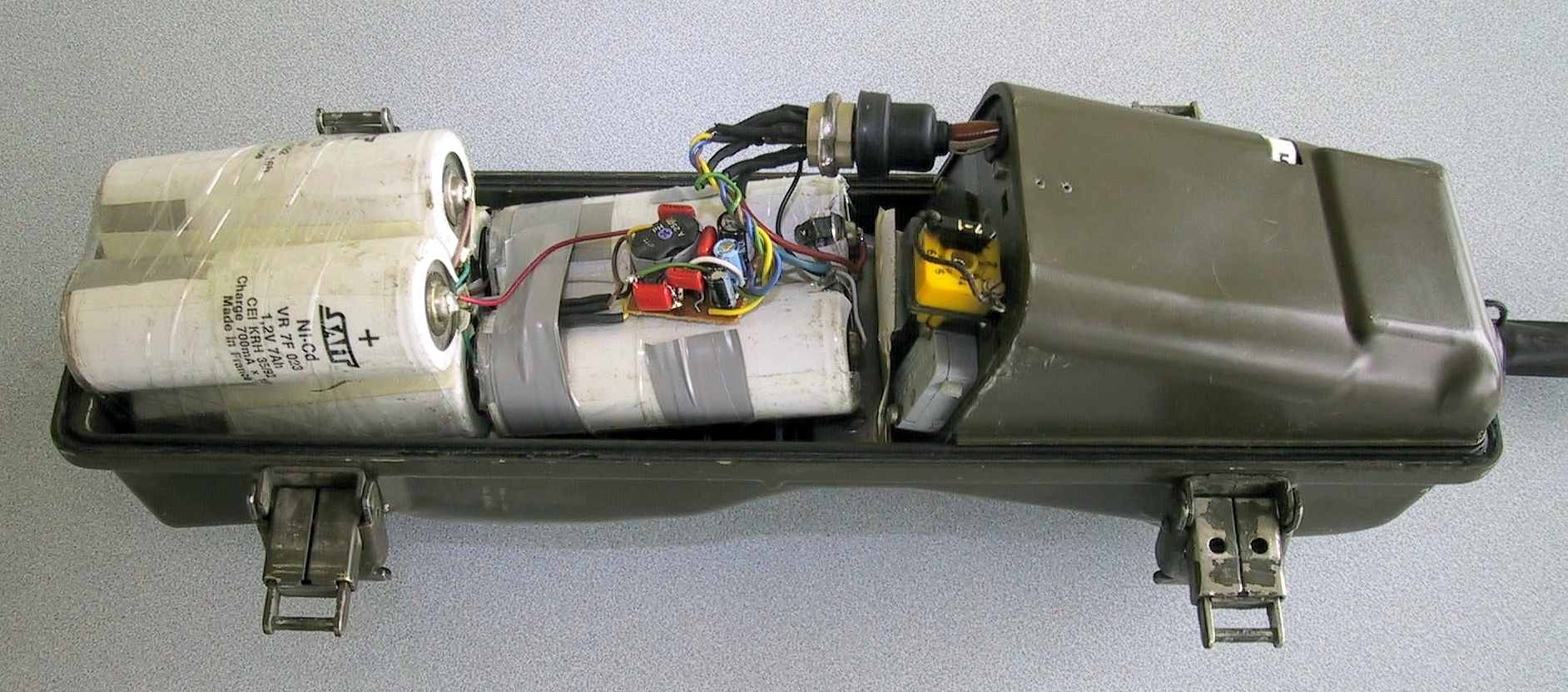
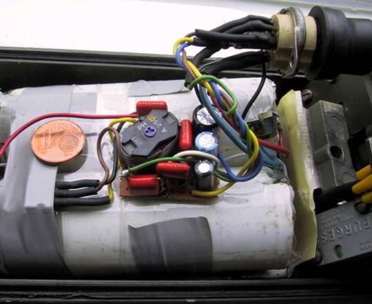
with their 110/220 volt AC/DC electric razors by people camping. Surplus I have built several sub miniature models based on this design for BC-611, PRC-6, PRC-26D etc. The later mentioned sets also need 45 volt Ht. Just fix a tap on the transformer, add another 1N4007, some associated filtering and your in business. If you need a negative Lt, use 2x 1N4148 as doubler and connect them via a capacitor (0,1 - 0,3uF) to the collector of the transistor. Performance Depending on the components used, the performance is very good. n >> 80% is possible, but some parts are critical, e.g. the ferrite transformer and capacitors. It is worthwhile to try other power transistors as well. As an experiment some weeks ago I tried a ferrite cable clamp as transformer (it is easy to wind) and it worked. After some experimenting I reached n=75% and that should be better. See photo and compare its size with a Eurocent. Furthermore I enclosed two photos of my PRC-6 inverter "built" in the battery box together with some large NiCad cells (Ub= 6-7,5v). Dimensions of the ferrite potcore: about 13x18x12 mm (3H1 ferrite Philips). Screening For portable Shortwave sets you may need to add ferrite chokes and appropriate decoupling capacitors. Use a closed metal box. Build it in an HF tin box (soldered "watertight") and use feed-trough capacitors for optimum results. For VHF purposes no additional screening is necessary. Maximum tested HT. By using an old TV- line transformer, I was able to obtain more than 300 volts at 120 mA out of this inverter. Performance was still better than 70%. Disadvantages Because this inverter starts rather slow, it may not be the right
choice for some CW-radios. |
|
Inverter basic design:
|
|
Experimental ferrite-clamp transformer;
|
|
Miniature inverter used in PRC-6/6;
|
|
Close up of inverter;
|


