The Wireless-Set-No19 Group
Royal Signals
www.royalsignals.org.uk
WS19, WS 19, 19 set, wireless set no 19, Royal Signals, ws18, ws22, ws38, Boatanchor, military radio, ws no 19, Manual Archive and Document Archive, Vintage Radio, Military, variometer

WS19 Logo

The WS 19 Established & Designed in England 1940
Royal Signals Established 28 June 1920

For the open exchange of information and opinions about collecting, restoring, maintaining and operating the Wireless Set No 19 and all other radios, as well as line and other forms of comms equipment, used by the Allied forces before, during and after World War II. For organising operating events with the broadest possible participation. Anyone interested in military communications equipment, vintage and modern, are most welcome.

The Manuals section of this site provides the largest publicly available historical archive of military communication documentation in the world. Documents are available for download to members and non-members alike, with no charge. However, to protect our investment in time and money, all documents are password protected. Please see here for instructions on obtaining passwords.

Joining The Wireless-Set-No19 Group and its e-mail reflector are FREE - CLICK HERE to join.


AIRMEC 871 Signal Generator

INTRODUCTION
The 871 is a universal piece of test equipment, also known as CT212 or OSCILLATOR TEST NO. 1 made in the United Kingdom in1956. It can generate RF signals in the HF range in seven bands, from 85 Kcs to 32 Mcs, with audio in the form of AM or FM modulation. The RF output is variable in the range from 1 microvolt to 100 millivolts. The AM modulation is fixed at 30% at 1 Kcs. The FM deviation is variable from 0 to 40 Kcs, and is available on the bands above 2 Mcs. There is also AF output on front panel terminals. The instrument contains seven B7G miniature valves. The rectifier is a CV493 (6X4) and the regulator is a CV287. All the other valves are CV138 (EF91 or 6AM6). The equipment is portable, and can operate from various voltages, 110-115-120 volts AC or 220-230-240 volts AC or 12 volts DC.

The frequency range is:

BAND    FREQUENCY
1             85 – 250 Kcs
2             250 – 700 Kcs
3             700 – 2000 Kcs
4             2 – 4 Mcs
5             4 – 8 Mcs
6             8 – 16 Mcs
7             16 – 32 Mcs

It is in a hermetically sealed cast aluminium case, similar to the Larkspur series of equipment. It is 8.75 inches high, 13 inches long, 10.75 inches deep, and weighs 30 pounds. It has a protective cover, which holds three cables. They are the AC power input cable, DC power input cable, and the signal output cable. There is a carry strap.


Picture 1: Front

There is a corresponding oscillator covering the VHF range, which is called OSCILLATOR TEST NO. 2 which covers the frequency range 20 Mcs to 80 Mcs.
It looks almost identical.

CONTROLS
The instrument has all controls and connectors on the front panel. These are protected when the cover is fitted. It has large easy to use knobs. The left hand side has the two power input connectors, for 12 VDC and for 110/ 240 VAC. At the top, is the CAL meter and a toggle switch to select AF or RF calibration. Next to this is the dial window, which is illuminated. At the right, is the coarse attenuator with the fine attenuator below it. Down the right hand side is the RF output connector, and below this is the AF output terminals. At the bottom is the desiccator. Along the bottom, is the ON/OFF switch, which also controls the modulation (AM or FM). It has an RF off position which is useful for determining the signal to noise of the device being tested. There is also an AF and an RF level control. In the middle is the main frequency tuning knob, which is large and has a good feel, but suffers from backlash. It has a graduated scale on its edge, but due to the rubber non positive drive mechanism, it is not useful. To the right is the band switch. To the left is the deviation control. At the bottom right side, on the flange, is a small disc that can be changed to indicate the working AC voltage, as is set on the inside tag strip.


Picture 2: Cover

DESIGN
The electronics is inside a heavy cast aluminium case, the same type as that used for the Larkspur range of radios. The generator is designed to be portable, rugged and waterproof. The mechanical design is modular. The power supply is a separate unit and is attached to the front panel. Four screws can be undone to remove the supply. The wire loom must then be unsoldered. The RF and AF oscillator is another unit, and also attached to the front panel. Four screws can be undone to remove the oscillator, and then the loom unsoldered. When working on the rear of the front panel, the screws can be undone, and the front panel can be folded down flat.


Picture 3: Modular

All the controls are on the front panel. They control the power supply and oscillator. Only two controls mechanically connect to the oscillator, the tuning and the band change. The tuning consists of a flat wheel on the front panel, which presses against a rubber wheel on the oscillator module. This is merely friction operated. It is easy to assemble and dissassemble, but there is some backlash in the tuning drive. The bandswitch engages with the switch in the oscillator, and needs to be aligned before re-assembly. The two attenuators are part of the front panel casting. They engage with a connector on the oscillator. There is an earthing grommet (a metal conductive washer) around this connector, and the manual warns against losing it.


Picture 4: Power Supply

The power supply contains a normal power transformer. It has taps that can be set for various AC mains voltages, from 110 to 240 volts AC. The tap is selected by soldering a wire on to a marked tag. There is a metal 3 pin connector used to supply the mains voltage. The power transformer provides 6.3 volts AC for the filaments of the valves. It also provides a 300 volt winding for the high tension (HT). There is a rectifier for the AC which produces the 350 volts DC. There is a choke and capacitor filter which results in 280 volts of smooth DC. There is also a vibrator (SV2) which uses the same transformer to provide the HT and filament voltage. It has a 2 pin metal connector on the front panel for the 12 volts DC input. There are several fuses on the power supply module. Two are for the AC mains input, and another two are for the DC power input. There is also a fuse for the HT output to the oscillator. These can only be accessed by opening the case.


Figure 1: Power Supply Circuit

At one stage, serious smoke erupted from the unit, initiating a panic turn off. There is a series R and C circuit across the HT secondary. C49 had short circuited, and burnt up R65, which released the large amount of smoke. The fuse eventually blew, but not in time to save the resistor.
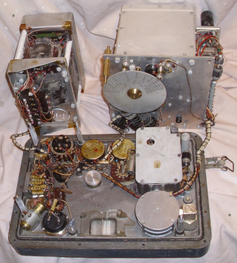
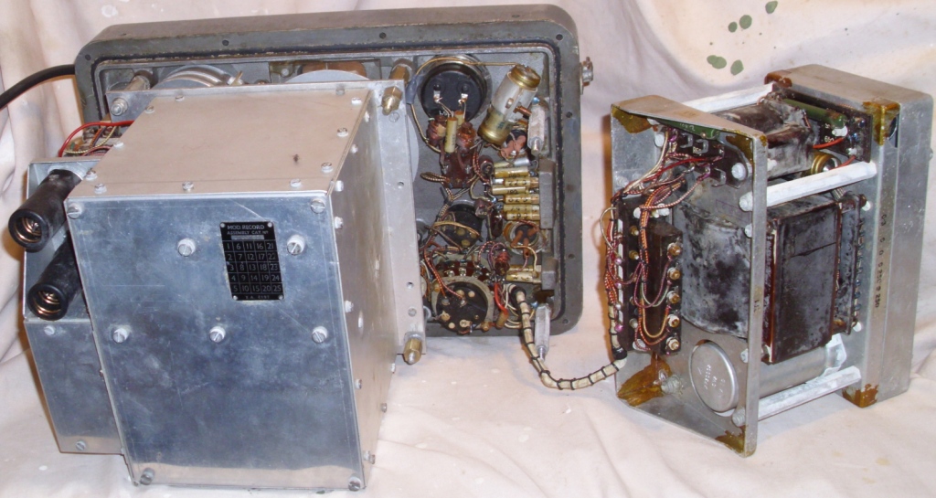
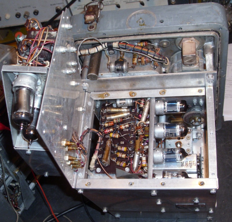
OSCILLATOR MODULE
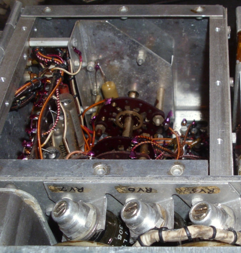
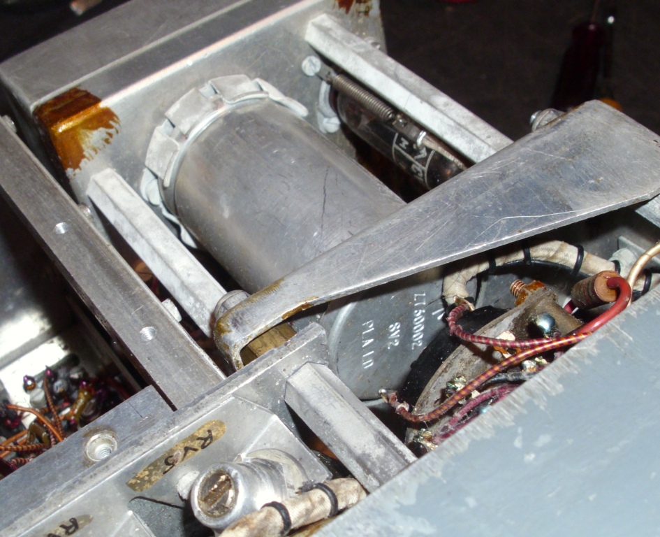
The oscillator is functionally arranged as two sections. The RF oscillator is contained inside a closed metal box. The AF oscillator is on the outside of this box. There is also a regulator that produces 150 volts DC for the RF oscillator.

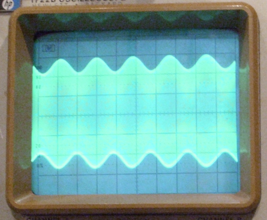
The AF oscillator valve uses a tuned choke (L7 and C24) to produce the 1 Kcs frequency. The waveform is available on two terminals on the front panel for external use. The AF level is rectified and shown on the front panel meter. 
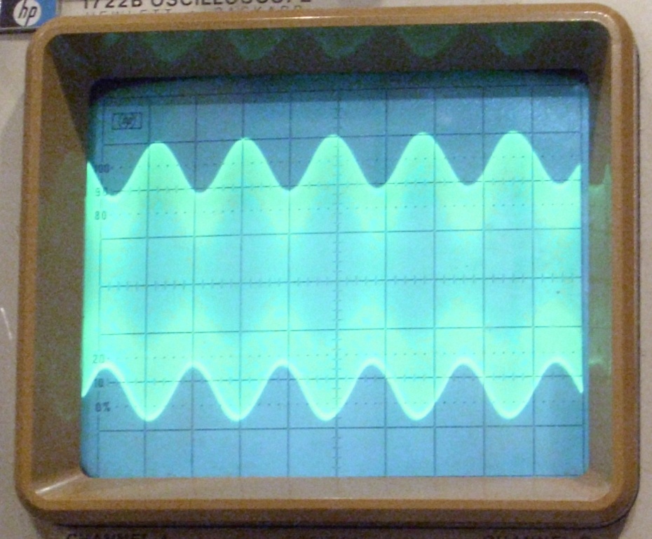
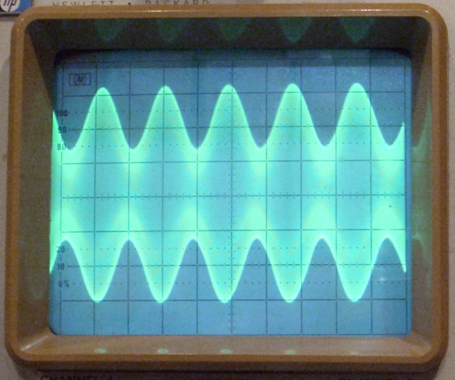
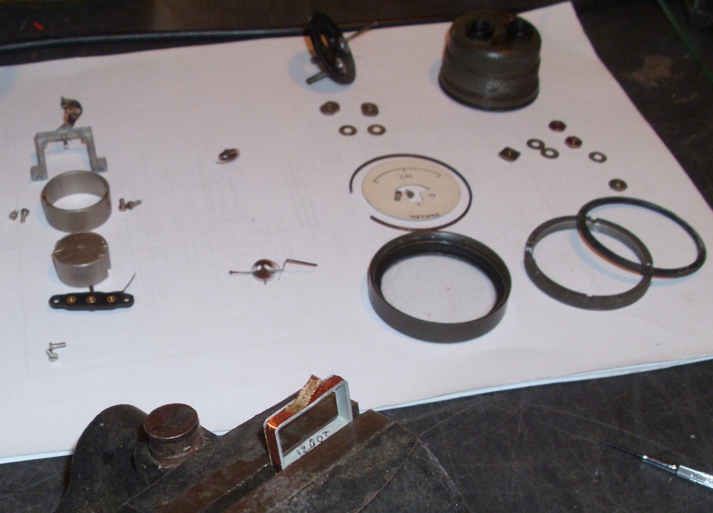
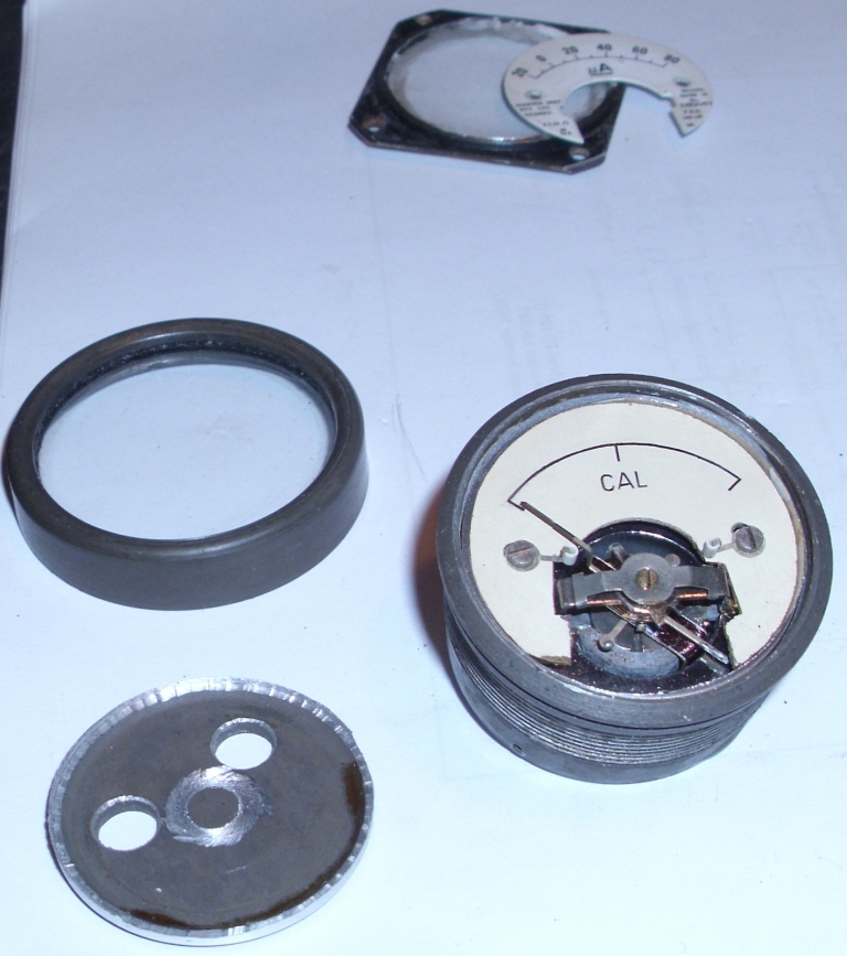
The AM modulation depth is set by adjusting the screen voltage of the AF oscillator using the SET MOD. front panel control. When the level is set to the CAL mark on the meter, the modulation depth is 30%, but it can be varied from about 10% to about 60% modulation. There is an internal preset control to calibrate the 30% level. AM modulation can be used on all bands.

When switched to FM modulation, the front panel DEVIATION control can be used to vary the FM from 0 to 40 Kcs. This control adjusts the amplitude of the AF applied to the reactance valve in the RF oscillator module. The reactance valve will act as a variable capacitance, and so vary the frequency of the RF oscillator. However, the amount of capacitance required to vary the RF oscillator frequency, is different for each RF frequency band, and changes as you tune from end to end of the dial range. To keep the deviation constant, two methods are used. There is a potentiometer ganged to the RF frequency tuning control. As the frequency is changed from one end of the dial to the other, the potentiometer adjusts the AF amplitude to keep the deviation constant for that band. Secondly, there is a preset for each band, to set the deviation amplitude for each particular band. The FM modulation can only be used on the four bands above 2 Mcs.

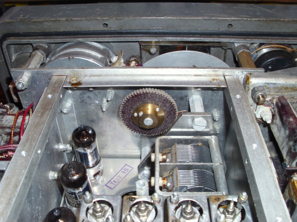
The RF oscillator uses an RF transformer to couple the plate to the grid, and a tuning capacitor to adjust the frequency. On the lower 3 bands, a dual gang tuning capacitor is used. On the upper 4 bands, only 1 gang is used, and the reactance valve is used in addition, but fixed for AM modulation, and with AF applied for FM modulation. The RF oscillator is coupled to a buffer, with a gain of approximately one. This then goes to the output amplifier valve, with adjustable gain, controlled by the screen supply variable from the SET CAR. front panel control, to set the output level. This control is used to set the amplitude to the CAL mark on the meter. AF is also applied to the screen to produce the AM modulation. The RF then leaves the oscillator box though a fixed connector, and enters the front panel attenuators. The RF amplitude is sampled at this point, and rectified for indication on the front panel meter.

The attenuator consists of three parts. The first part is a “coarse” resistive divider, with 5 positions, that produces 10 dB reduction at each position. The second attenuator is a “fine” resistive divider, with 11 positions, that provides 2 dB reduction at each position. The third attenuator is 
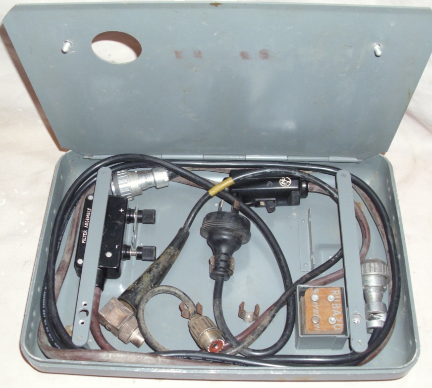
external to the instrument, and is in the RF output cable. This is really a terminator (TERMINATING UNIT No.3), and provides 75 ohm output or 7.5 ohm 
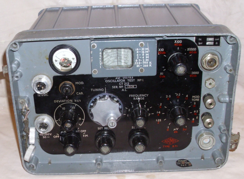
output. The attenuators are labeled with a voltage scale (in black) and a dB scale (in red). Using the black scale, the bottom attenuator control can be set from 1 to 10 microvolts. The top attenuator, can then select X1, X10, X100, X1000, and X10000. You have to do a mental calculation to understand that this means that the output level is 1-10, then 10-100, then 100-1000 microvolts. Then the next position is 1-10, then 10-100 millivolts. Using the alternative red scale, the bottom attenuator control can be set from 0 to 20 dB in 2 dB steps. The top attenuator, can then select 0, 20, 40, 60 and 80 dB. These can be added together to give a 100 dB range, but relative to what? It means that with no attenuation, the output level is +100 dB greater than 1 microvolt. This is backwards thinking from the way I use attenuators. I normally start with 0 dB as maximum output, and then work down in negative dB steps. I found this dB scale slightly confusing. It took some getting used to. I had to always remember that with both knobs fully clockwise, there was maximum output. I gave up trying to use dB, and only used the voltage scales.


Figure 2: Oscillator Circuit

Some attention has been focused on the sealing of the generator, to prevent RF leakage, especially important when attempting to use very low levels of RF output. There is a large flange on the front panel to case join, with many screws. The RF attenuators are enclosed in cast alloy boxes, and are part of the front panel casting. There is filtering on the AC and DC power lines, to prevent leakage from these.

RESTORATION
I had two of the generators, so it was helpful to compare levels and voltages. There was one AC mains cord, and one DC power cord. The DC cord appeared to work and the vibrator started, when 12 volts DC was connected. The vibrator was missing from the other generator. The AC cable was hard and cracking, so the connectors were cut off and the cable was discarded. A new cord was made for each generator.

The aluminium case is normally sealed closed with 10 screws and a gasket, and has a desiccator to keep the insides free from dirt and moisture. Some previous owner had drilled many holes in the case, possibly to allow cooling. This has exposed the internals to the elements. The case was opened, and it was very clean inside, despite the holes. The insides are clean, and dry, with no dirt or corrosion. There was no obvious damage, burning, or modification. There was a new wire run in two places, next to a loom, indicating a broken wire within the loom. There were two new capacitors fitted, indicating repairs in the past. The paint was in poor condition, so the case was repainted. There had been rubber feet attached to the bottom of the case, but these had perished, so new feet were added.

AUDIO OSCILLATOR
The AF oscillator was not working, so there was no modulation. It was found that the oscillator coupling capacitor C23 was leaky and allowing HT plate voltage to appear on the grid of V5. A new capacitor was fitted, which removed the positive grid voltage. The valve now oscillated and there was -6 volts on the grid, and a good sine wave on the plate. The amplitude of the AF oscillator was not sufficient to allow the meter to be set to the CAL position, and consequently, there was less than 30% AM modulation. The tuned circuit capacitor C24 was replaced, and there was now adequate amplitude (100 Vpp on the output terminals), and the frequency was close to 1 Kcs.


Picture 5: Modulation
(SET MOD. control at 45 degrees = 10% modulation)


(SET MOD. control at CAL = 30% modulation)


(SET MOD. control at 135 degrees = 60% modulation)

The AF level was not reading on the other meter, which turned out to be a faulty rectifier. It uses those early Westinghouse WX6 crystal diodes. I replaced it with a 1N4004 which will work at 1 Kcs satisfactorily. The meter level needed recalibration with the preset RV5.

RF OSCILLATOR
The RF oscillator was not working, so voltages the were checked. The regulated 150 volts was down to 20, and the regulator valve was not alight. The RF box was opened, by removing the 11 screws on the top panel. This revealed the valves, coils and tuning capacitors, but no components. The bottom panel was taken off, by removing 12 screws. This revealed the wafer switch and some components, but not the valve bases. The side panel had its 11 screws removed, and it hinged out, as it had the AF oscillator and regulator on it. This revealed the valve bases and some components. It was all very accessible. A shorted capacitor C42 was replaced and the regulated voltage returned to 150 and the RF oscillator was now working. The meter could now be set to the CAL position, on all bands. The other generator now stopped working, also with low regulator voltage. The same C42 had failed in this unit, so it was replaced. There was still no RF output. There was no voltage on the screen of the reactance valve. A wire had broken off, as I must have disturbed it. It was rejoined, but there was no change. I tried other bands, and there was some output on bands 6 and 7. It appeared as though the oscillator and buffer were working. I replaced the coupling capacitor C109 between the buffer and the output amplifier. There was output on all bands now. The capacitor appeared to be open circuit, but letting a little through on the higher bands. I checked the RF frequency calibration, and bands 1, 3, 6 and 7 were good. The other bands were high in frequency, and it would not oscillate on the lower part of those ranges. I replaced the HT bypass capacitors C32 and C60, which are also the RF return for the tuned circuits. These were open circuit. All bands were now on frequency. I measured the RF output level, and it was 1 milli-volt at the CAL position on the meter.


Picture 6A: Inside of RF box (top)


Picture 6B: Inside of RF box (underneath)


Picture 6C: Inside of RF box (side)

METER
One generator had a working meter, and it appeared that it was a replacement. The other meter was not reading reliably, and sometimes it was intermittent. It eventually failed.

The meter was removed and the case opened. It appeared that the movement was open circuit, so the meter was dismantled. The moving coil was loose, but could still rotate. With magnification, it appeared that one of the pivots, was insecure. So the hairsprings were unsoldered, the top bearing bridge was unscrewed, and the magnet removed. It could be seen that the bottom pivot was only partially attached. When touched by tweezers, it fell off. It was glued to the rotating coil, and the glue had failed with age. The top pivot was examined, and with a little touch it also came adrift, as the glue was poor there as well. The wire ends of the coil winding were teased out, but there was no continuity. I decided that there was nothing to loose, so I fitted the coil to my coil winder and started unwinding the wire. It was very fine, and measured about 0.04 mm, which makes it about 48 SWG wire size. The wire broke several times, but after removing about 100 turns, both ends were unable to be located, and there was still plenty of wire on the coil. I abandoned the idea of rewinding the meter coil.


Picture 7: Old Meter

A similar size meter was found in the junk box. It was 100 micro amps FSD, and working, but had an offset zero. Also, the scale was wrong so it needed to be changed. The meter was totally sealed, so I put it in the lathe and used a sharp tool to cut the front flange off. The old scale was trimmed so that it fitted the new meter, and screwed on. The zero offset was adjusted. The new meter was slightly smaller that the old one. I put the old meter empty case in the lathe, cut off the rear end, and enlarged the inside so that the new meter fitted. I then glued the new meter in place, and fitted on the old glass face. It looked perfect and original from the front. The meter was fitted to the instrument, and wired in. It now displayed the correct levels, and the CAL function could be used.


Picture 8: New Meter

ATTENUATOR
The coarse attenunator had a dead position in its range. It was dismantled and cleaned. All the resistors were measured and found to be correct. The contact spring was retensioned. It was reassembled, and now worked properly.

CONCLUSION
The generator covers a wide frequency range, and is useful for field repairs, especially for low frequency IF alignment. It is portable and water proof. It has large knobs which are easy to use. It looks good and professional. The inside construction is modular, with laced forms, and sealed attenuators. It will run from a range of voltages. The meter appears to be a weak point in this instrument, as one had been replaced, and the other failed during use. The red attenuator scale in dB I found confusing. The large tuning knob has backlash, and a non-useful graduated edge scale. An external audio input would have been useful. The internal wiring is not very flexible and can break. The vibrator can is close to the mains switch.


Picture 9: Vibrator and Mains Switch

The dial window could be larger, and the dial easier to read. There is no band indicator, just the small numbers next to dial. The capacitors could be better, some go short circuit, while other go open circuit. The power supply could be mounted on its own mounting studs, instead of sharing two studs with the RF oscillator. If it was, then the RF oscillator box could easily be removed, without having to remove the power supply first. Overall, it is a nice generator, and well designed.

REFERENCES
EMER Z 340 TECHNICAL DESCRIPTION
EMER Z 341 OPERATING INSTRUCTIONS
EMER Z 342 TECHNICAL HANDBOOK, PART 1
EMER Z 342 TECHNICAL HANDBOOK, PART 2
EMER F 144 FIELD AND BASE REPAIRS

This Description was written by Ray Robinson for his own
website and is reproduced here with his kind permission.

INDEX