|
Chassis Views |
||||
 |
 |
 |
||
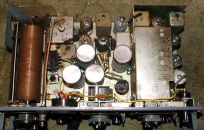
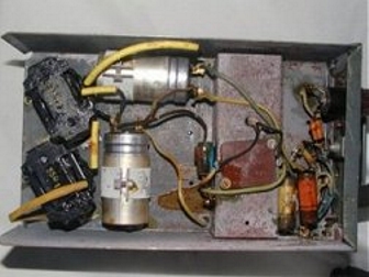
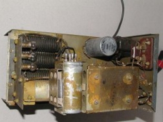
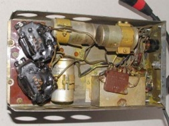
PSU No.4 Mk1* |
PSU No.4 Mk1* |
PSU No.4 Mk1* |
||
 |
 |
 |
||
PSU No.4 Mk1* |
PSU No.4 Mk1* |
PSU No.4 Mk1* |
||
 |
 |
 |
||
|
WS22 inside top |
Underside of WS22 chassis with the base plate in
place Click image for larger view and base plate dimensions. |
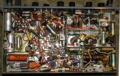
WS22 bottom, screen removed |
||
 |
|
 |
||
 |
|
 |
||
|
|
||||
|
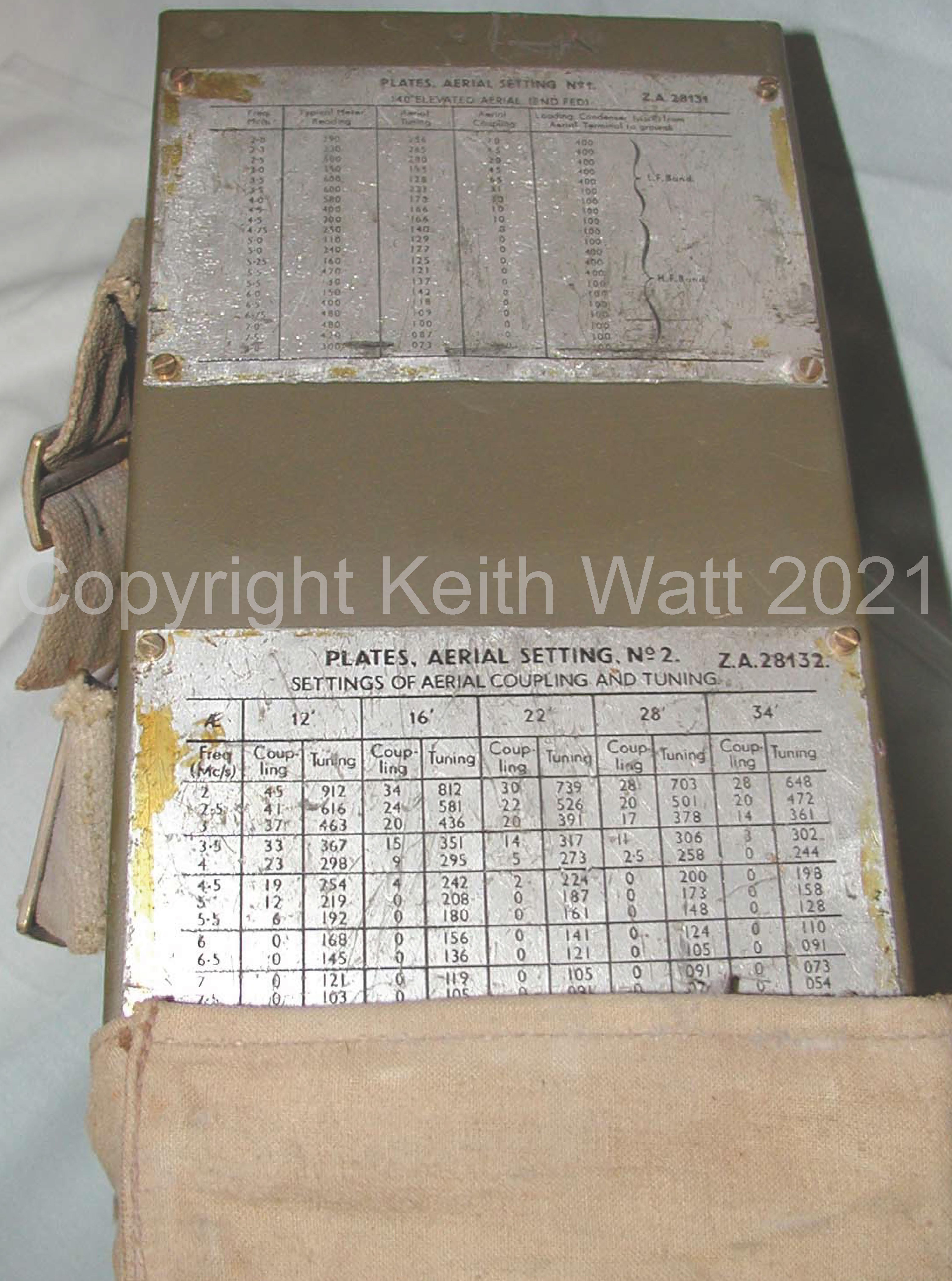
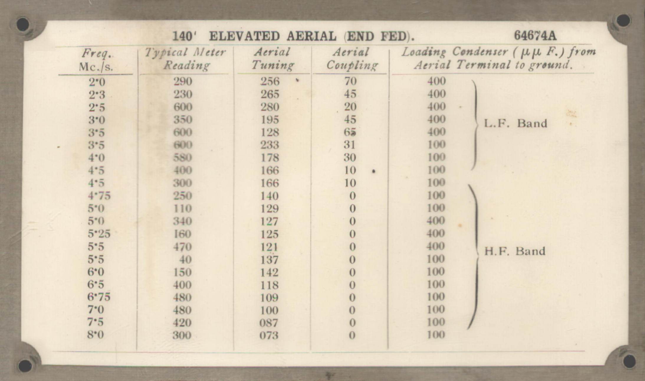
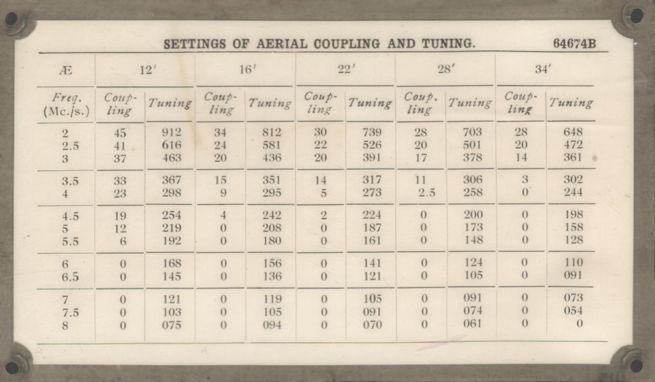
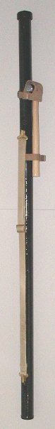
140FT Elevated Aerial End Fed |
Settings of Aerial Coupling & Tuning |
|||
 |
Click on images for larger view |
 |
||
|
|
||||
|
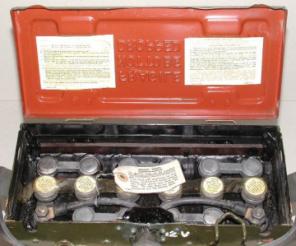
12 volt, 22Ah
Lead Acid battery |
||||
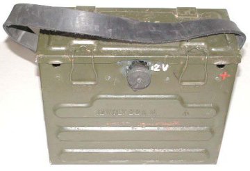 |
12 volt, 22Ah Lead Acid battery Niphan power socket can be seen This battery has never been filled |
 |
||||||||||||||||||
|
|
||||||||||||||||||||
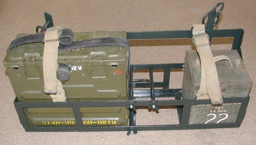 |
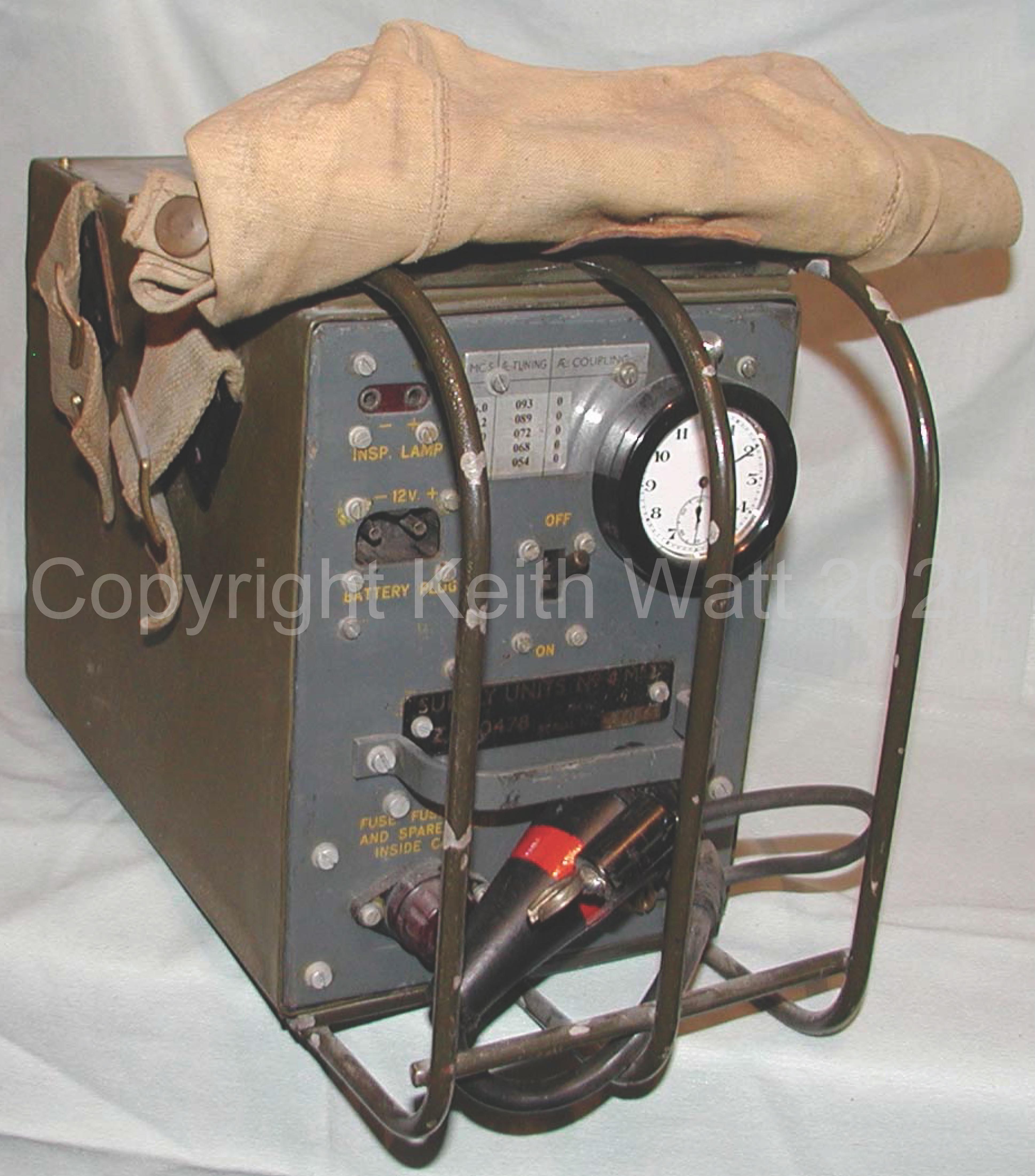
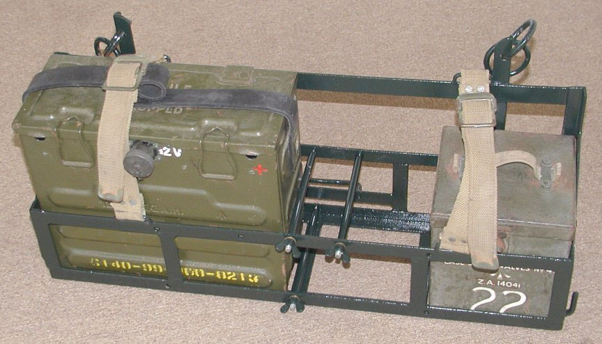
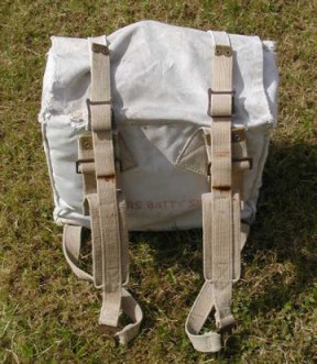
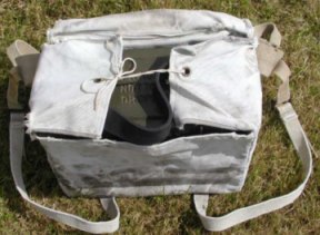
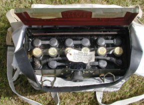
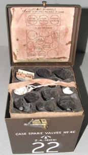
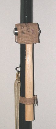
Front view showing the 22 Ah battery
and the WS22 spave valve kit in place |
 |
||||||||||||||||||
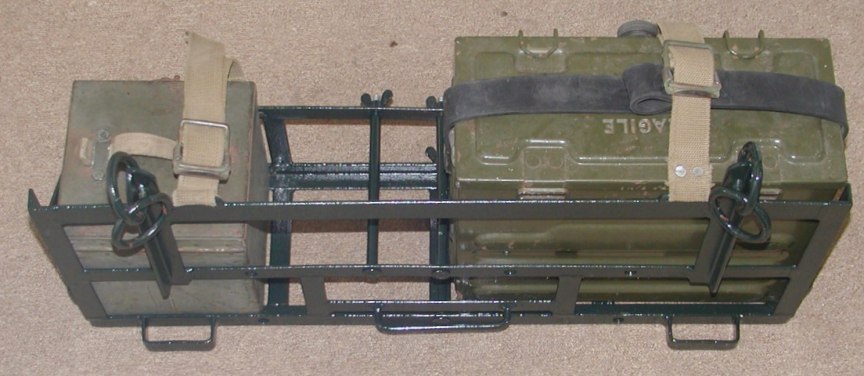 |
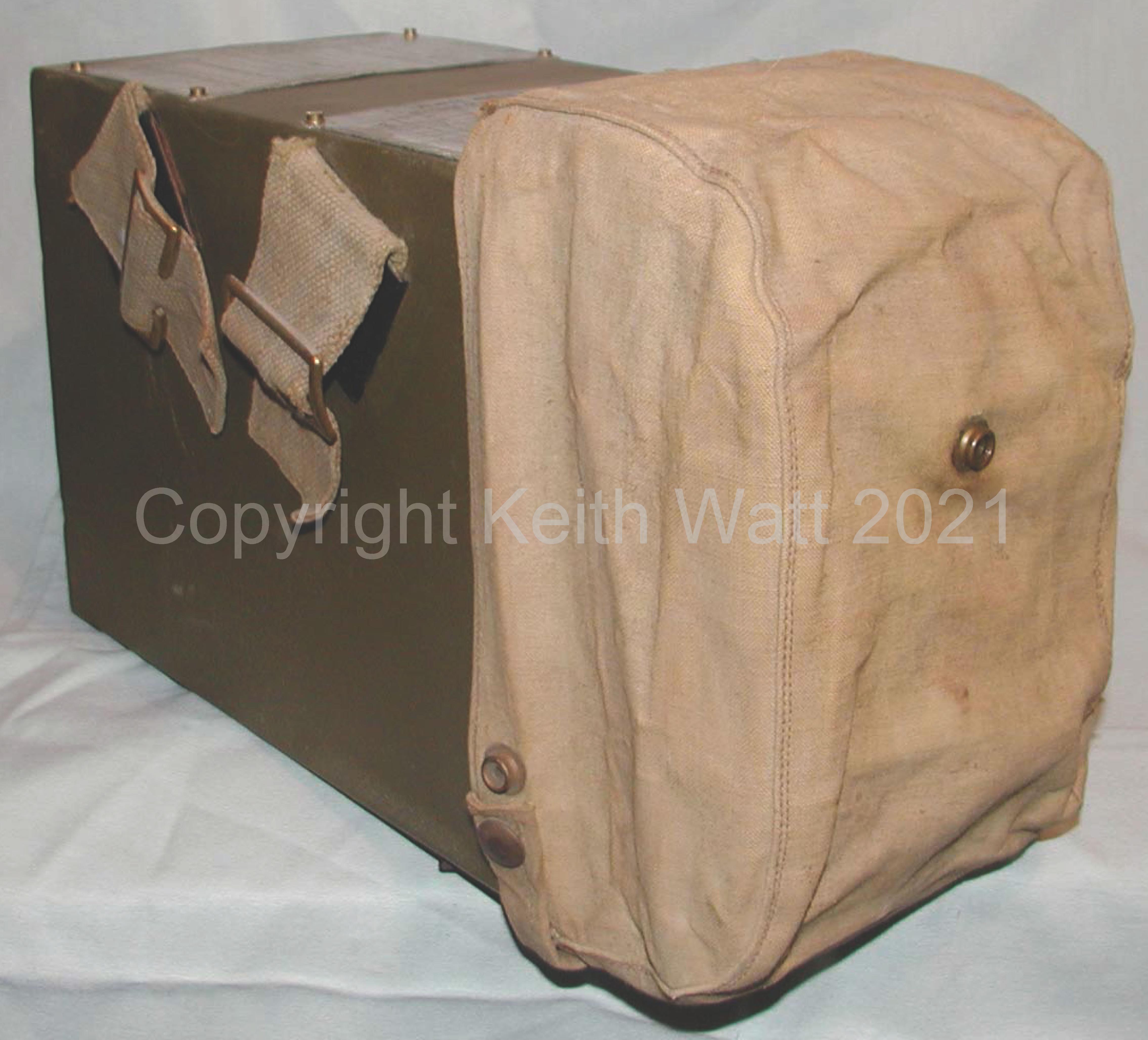
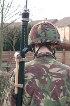
Back view showing loops that attach the
carrier to the saddle on the animal, the animal normally being a Mule. |
Click on pictures of carrier
for larger images.
|
||||||||||||||||||
|
|
||||||||||||||||||||
|
||||||||||||||||||||
|
Pocket Volt Meter
250v No.2 ZA 7372
|
||||||||||||||||||||
|
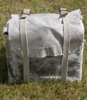
Meter storage bag dated 1944 |
|
Meter storage bag dated 1944 |
||||||||||||||||||
 |
||||||||||||||||||||
|
|
||||||||||||||||||||
|
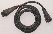
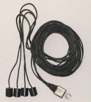
5 point audio extension lead
|
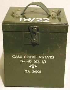
Spare Valves
Kit, No. 4G Mk 1/1 ZA. 26925
|
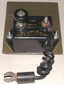
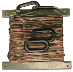
X55 Aerial capacitor
|
|
 |
 |
 |
 |
|
5 point audio extension lead, used to extend the length of the lead to headphones or the power cable between the PSU and Wireless Set. |
WWII Wireless Set No. 22 Spare Valves Kit, No. 4G Mk 1/1 ZA. 26925. |
X55 Aerial capacitor, used to protect the operator
from high voltage shocks should the radio aerial come into contact with
over head wires.
|
|
|
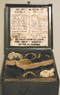
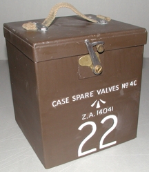
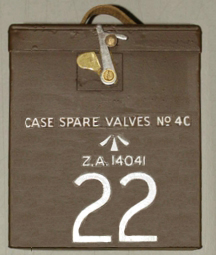
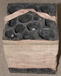
Spare Valves
Kit, No. 4C ZA. 14041
|
|||
 |
 |
 |
 |
|
WWII Wireless Set No. 22 Spare Valves Kit. |
Rubber insert that holds and protects the valves.
|
||
|
|
|||
|
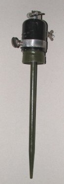
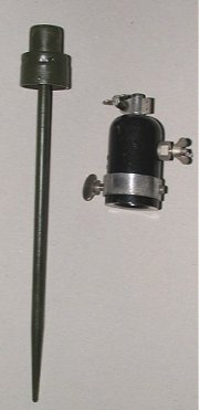
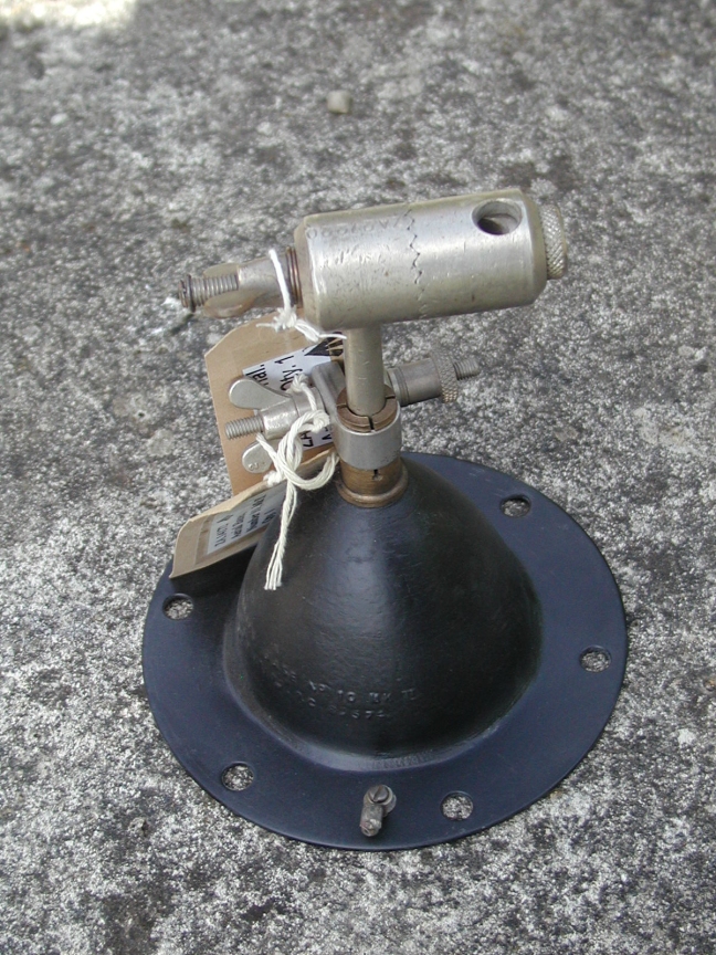
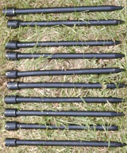
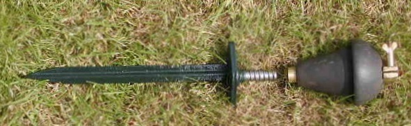
Aerial Base No.11
& ground spike
|
||||
 |
|
 |
||
|
Aerial Base No.11 (ZA11009) & ground spike(ZA11010),
assembled.
|
|
Aerial Base No.11 (ZA11009) & ground spike(ZA11010),
shown separate.
|
||
|
|
||||
|
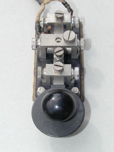
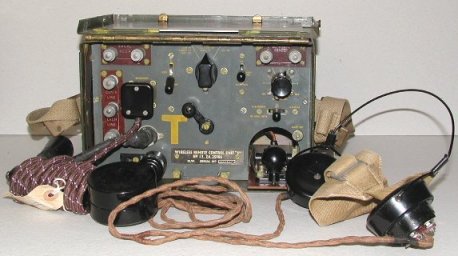
Wireless Remote Control "F" Unit 1
|
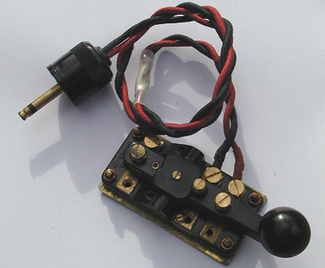
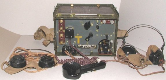
Wireless Remote Control "F" Unit 2
|
 |
 |
|
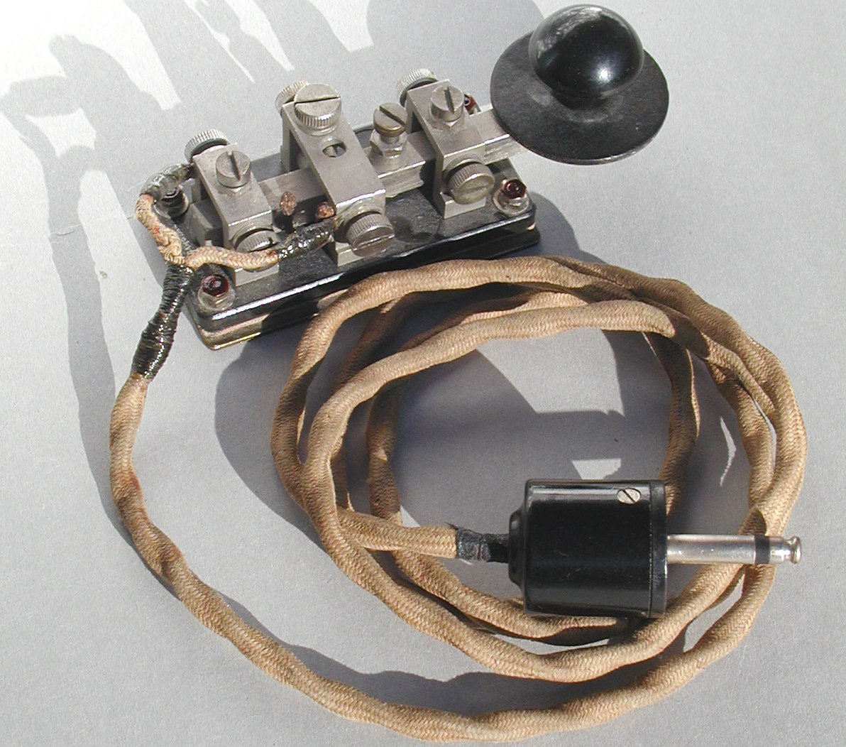
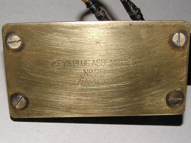
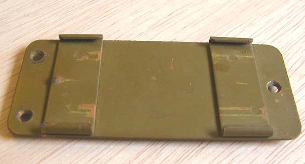
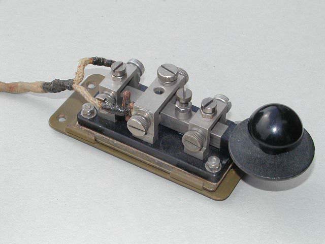
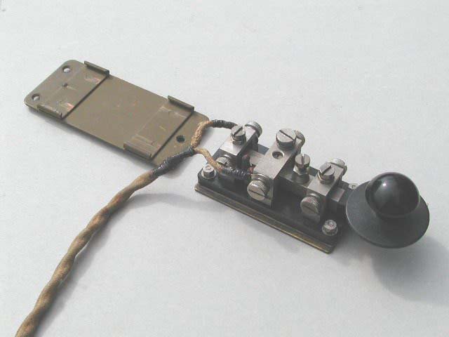
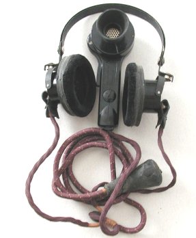
Wireless Remote Control "F" Unit 1, |
Wireless Remote Control "F" Unit 2,
complete with DLR headphones and No.8 mic. The unit's Morse key can also be seen in the bottom right corner of the case. |
 |
 |
|
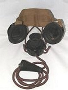
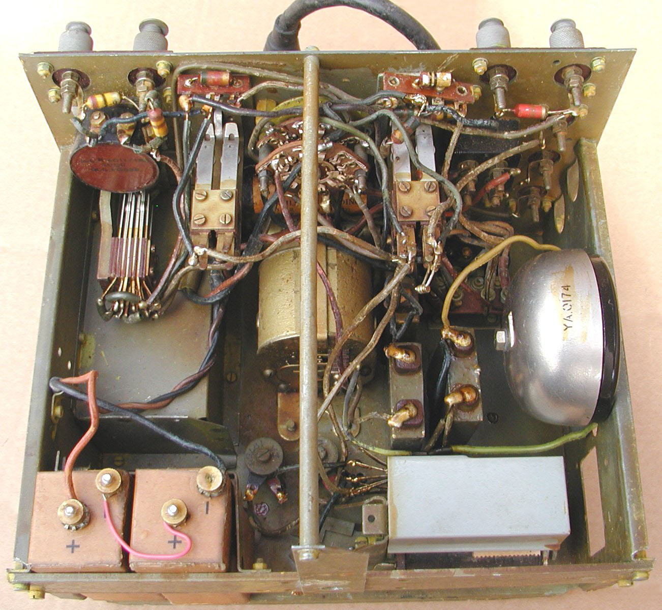
Wireless Remote Control "F" Unit 1, internal
view with the 2 1.5 volt X cells for powering the mic circuit. |
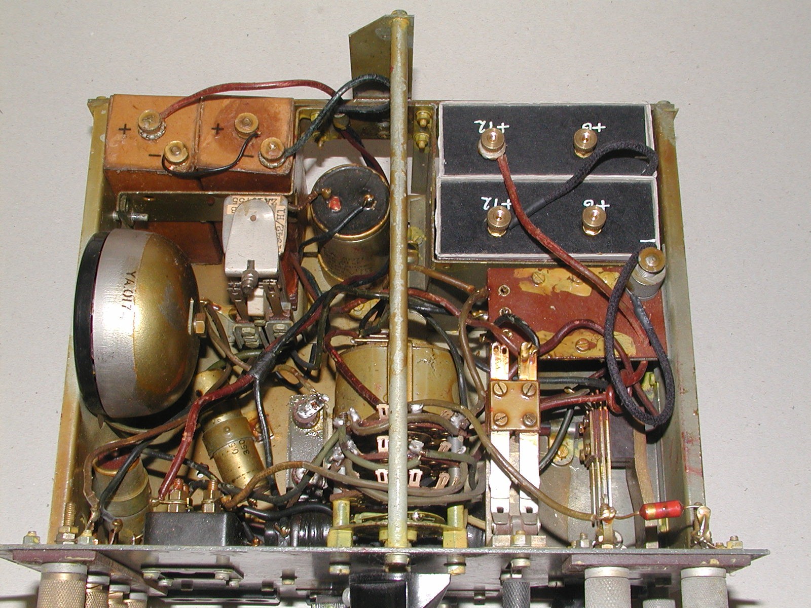
Wireless Remote Control "F" Unit 2,
internal view with the 2 1.5 volt X cells for powering the mic circuit and the 24 volt battery for powering the keying circuits. |
|
|
|

 |
|
 |
||
|
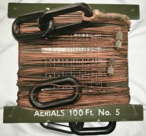
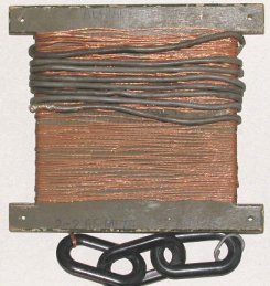
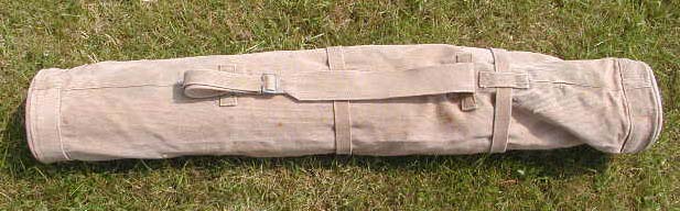
"Aerial 100 foot No.5" ZA 27624 with its storage
bobbin and insulators, you can just make out the tuning chart under the wire. Dated 1943. |
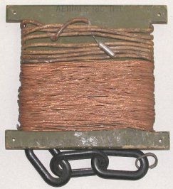
"Aerial 100 foot No.5" ZA 27624, as viewed from the back. |
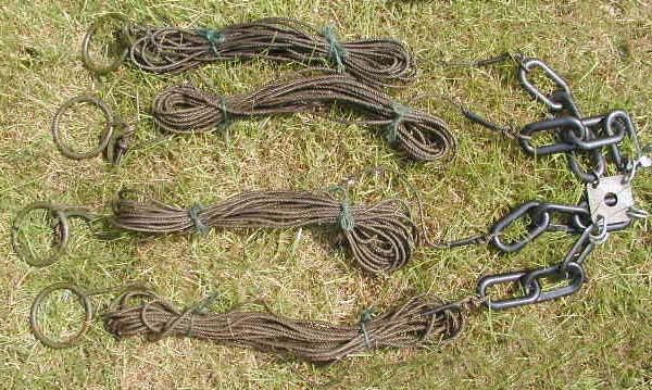
Counterpoise used in conjunction with the aerials
for the Wireless Set No.22. Consisting of 4 thick wire radials that are connected to the ground post of the radio. |
||
 |
 |
 |
||
|
"Aerial 250 foot No.1" with storage bobbin
& insulators. Frequency range marked on bobbin is 2 Mc - 2.65 Mc. |
"Aerial 185 foot No.1" with storage bobbin
& insulators. Frequency range marked on bobbin is 2.6 Mc - 3.5 Mc. |
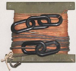
"Aerial 150 foot No.2" with storage bobbin
& insulators. Frequency range marked on bobbin is 3.45 Mc - 4.5 Mc. |
||
 |
 |
 |
||
|
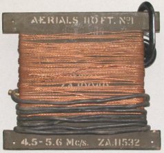
"Aerial 110 foot No.1" with storage bobbin
& insulators. Frequency range marked on bobbin is 4.5 Mc - 5.6 Mc. |
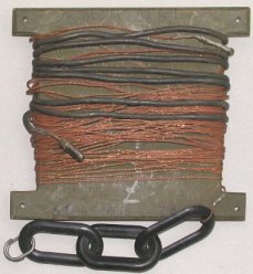
"Aerial 90 foot No.1" with storage bobbin
& insulators. Frequency range marked on bobbin is 5.5 Mc - 6.5 Mc. |
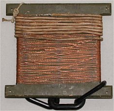
"Aerial 70 foot No.1" with storage bobbin
& insulators. Frequency range marked on bobbin is 6.6 Mc - 8 Mc. |
||
|
|
 |
 |
||
|
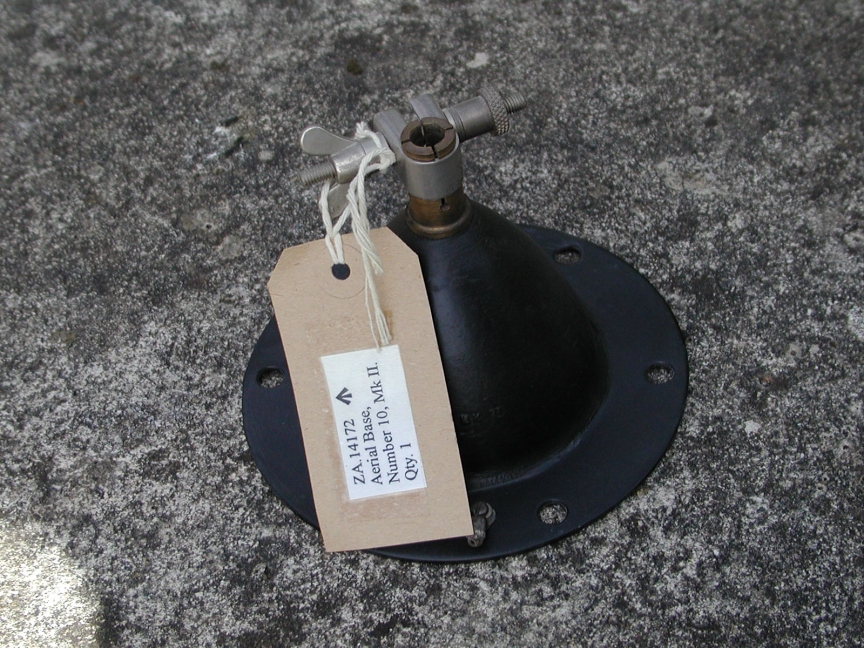
Aerial Base No. 10 Mk II ZA 14172 |
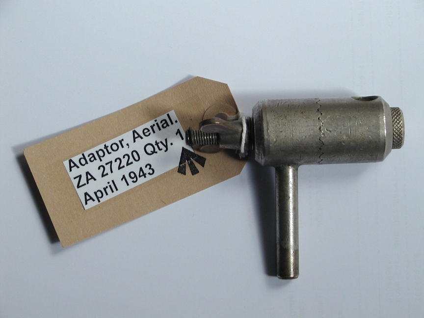
Aerial Base No. 10 with Aerial Adaptor No. 1, ZA27220 |
Aerial Adaptor No. 1, ZA27220, allows F Rods to |
||
|
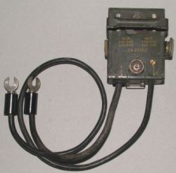
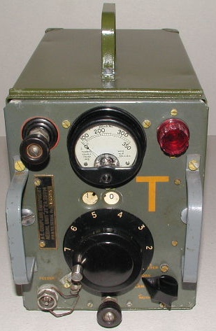
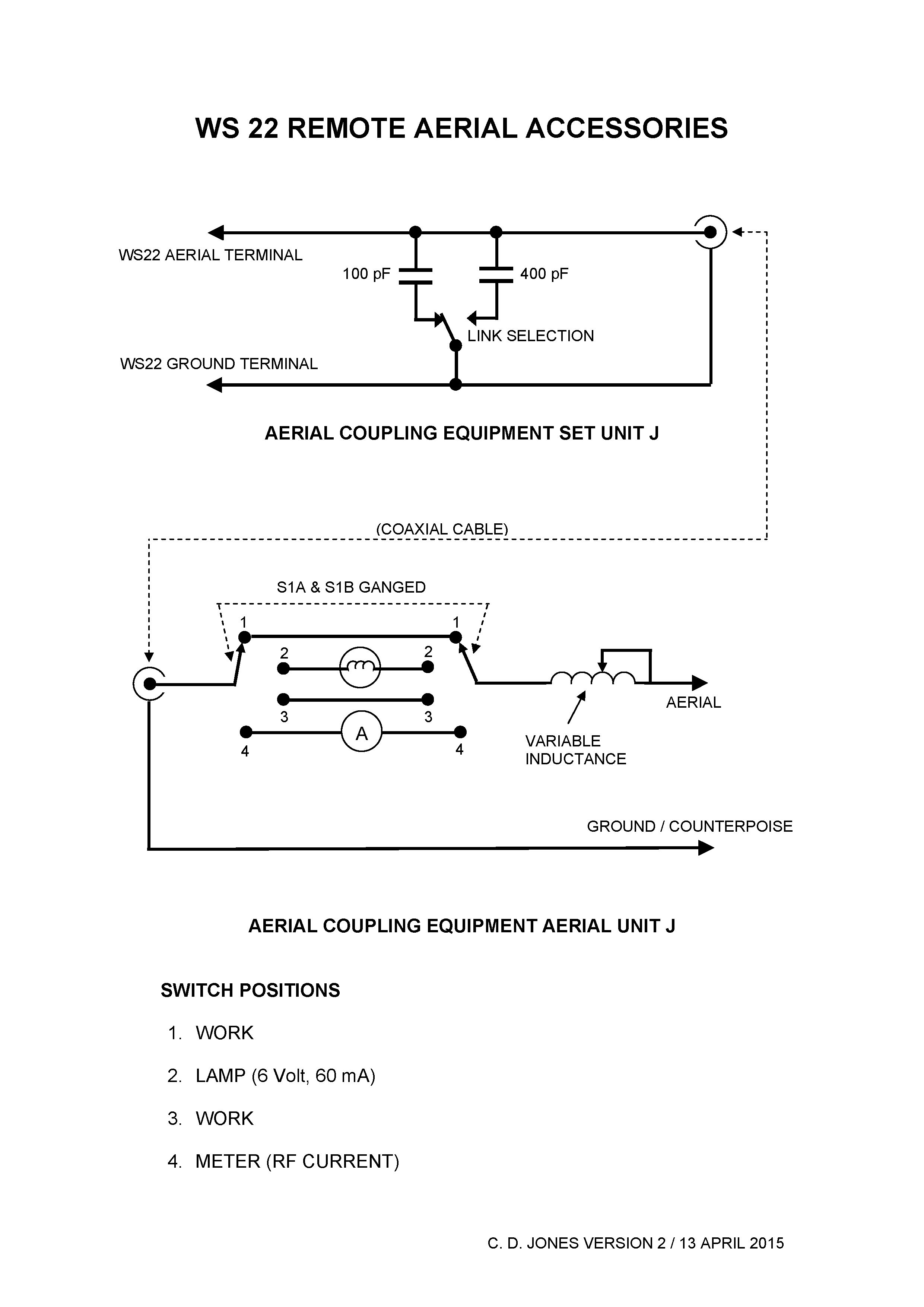
Antenna Coupling Equipment, Set
Unit J, ZA 27322 Click Here for Circuit Diagram of Set Unit J and Remote Unit J |
||||
 |
 |
 |
||
|
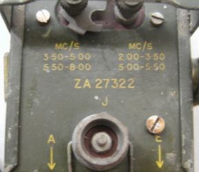
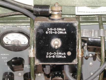
Antenna Coupling Equipment, Set Unit J,
ZA 27322. Close up view showing the Pye coax socket & the frequency range switch. |
Antenna Coupling Equipment, Set Unit J, |
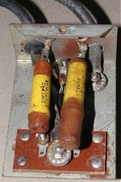
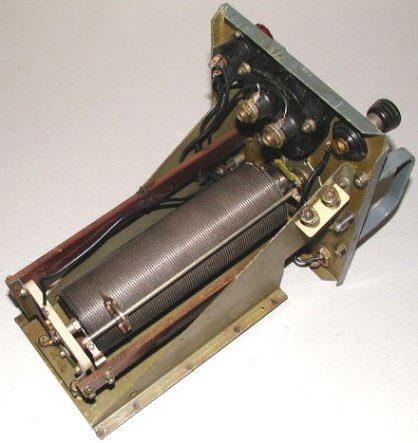
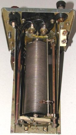
Inside View of the Antenna Coupling
Equipment, Set Unit J, ZA 27322. |
 |
|
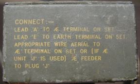
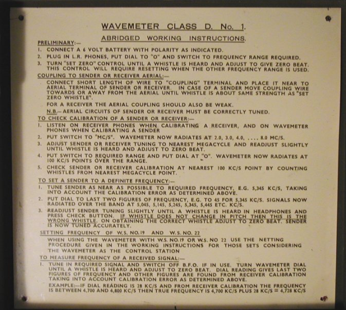
Instructions on the end of the case on how to use
the Set Unit H/J.
|
 |
|
Inside View
|
 |
|
Antenna Coupling Equipment, Aerial Unit J, ZA25914. This is the remote aerial tuner for the Wireless Set No.22. |
|||||||||||||||||||||||||||||||||||||||||||||||||||||||||||||
 |
 |
||||||||||||||||||||||||||||||||||||||||||||||||||||||||||||
 |
 |
||||||||||||||||||||||||||||||||||||||||||||||||||||||||||||
 |
 |
||||||||||||||||||||||||||||||||||||||||||||||||||||||||||||
|
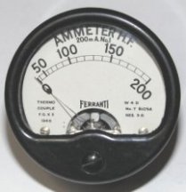
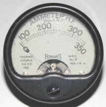
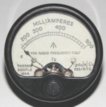
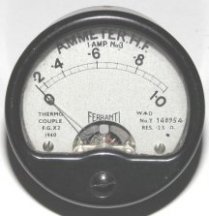
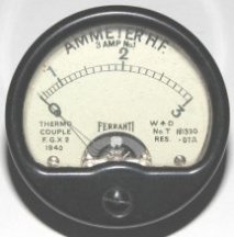
RF Ammeters used in the Aerial Coupling Equipment, |
|||||||||||||||||||||||||||||||||||||||||||||||||||||||||||||
|
|
|||||||||||||||||||||||||||||||||||||||||||||||||||||||||||||
|
|||||||||||||||||||||||||||||||||||||||||||||||||||||||||||||
|
|
|||||||||||||||||||||||||||||||||||||||||||||||||||||||||||||
|
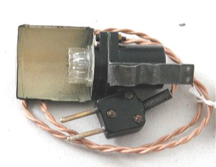
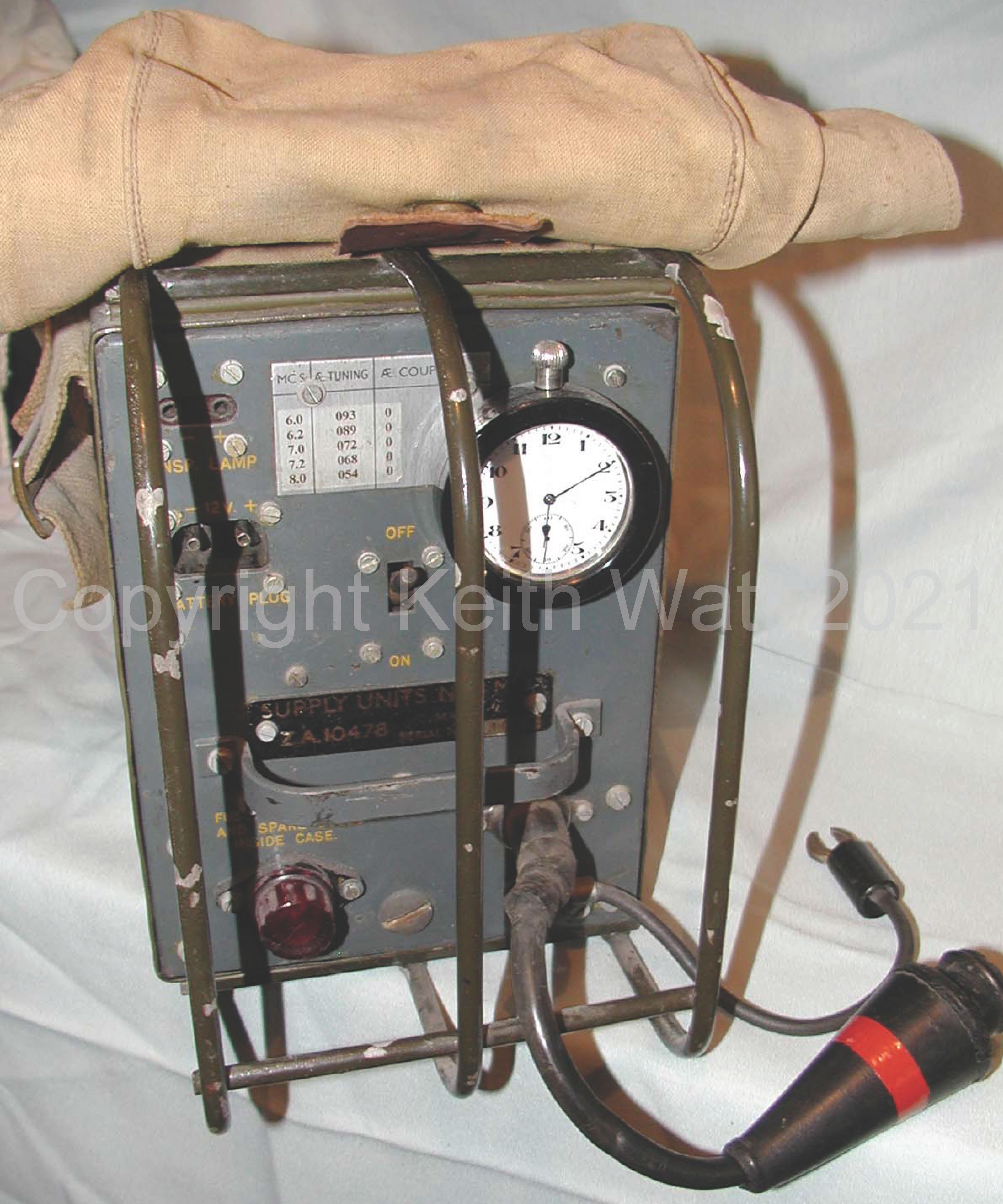
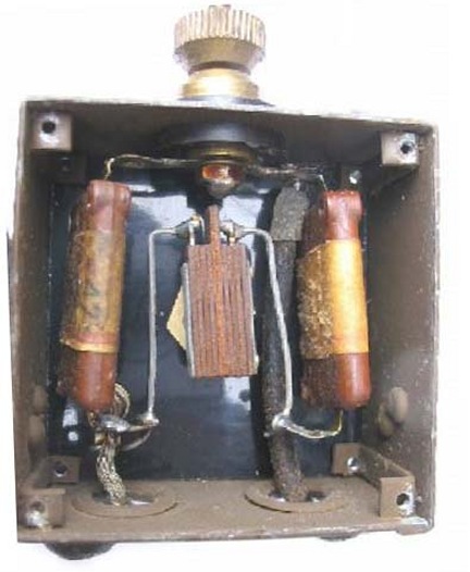
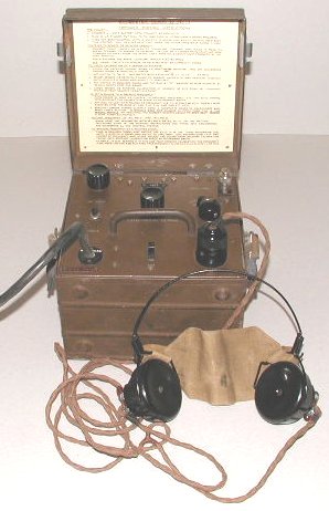
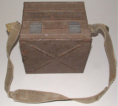
Wave Meter, Class D, No.1 MkII, ZA-14269 Powered from 6 volts this unit was used to pre-set a Wireless
Set No.22 to |
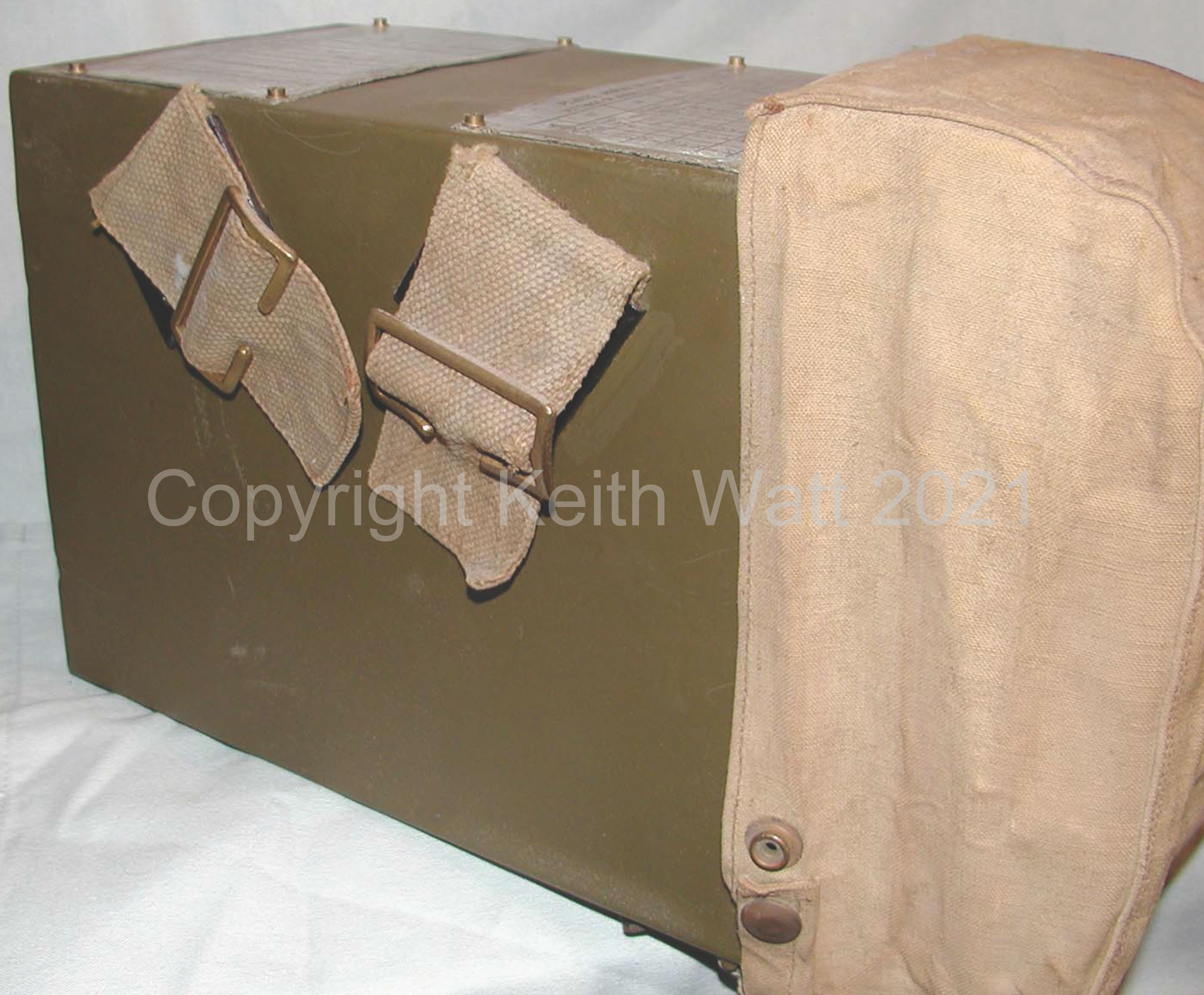
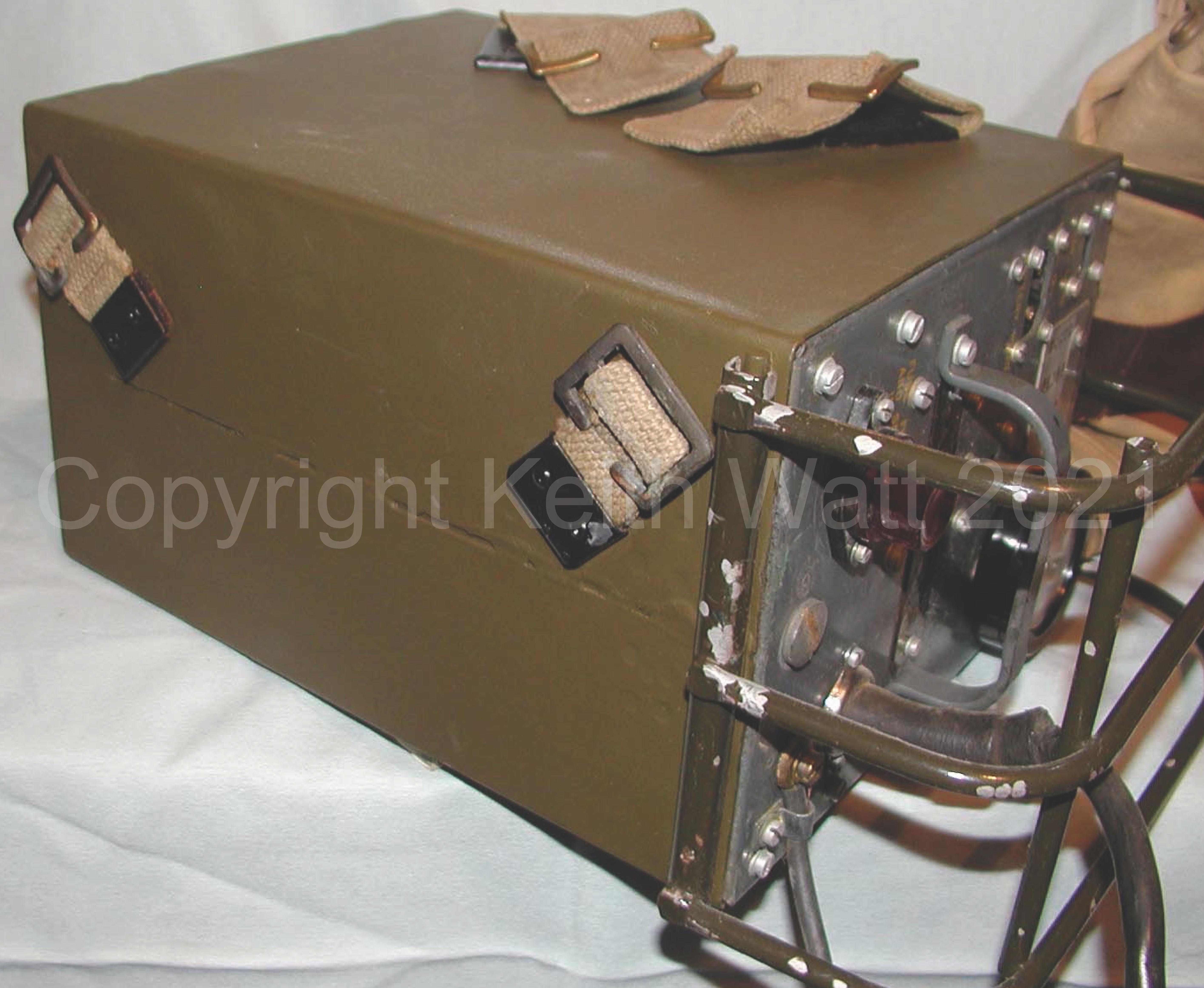
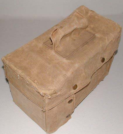
Transit case No. 7 containing Class D Wave Meter No. 1 Mk II |
||||||||||||||||||||||||||||||||||||||||||||||||||||||||||||
|
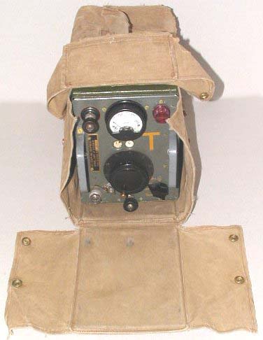
Open Transit case No. 7 containing Class D Wave Meter No. 1 Mk II |
Wave Meter all set up and in use. |
||||||||||||||||||||||||||||||||||||||||||||||||||||||||||||
|
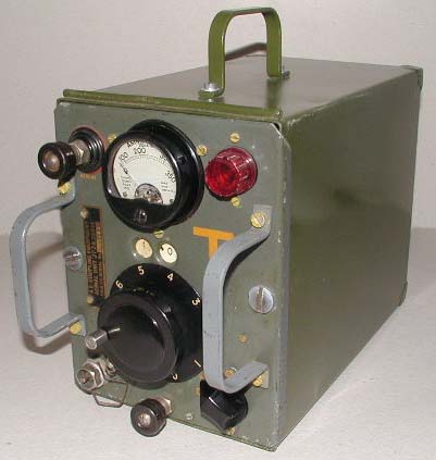
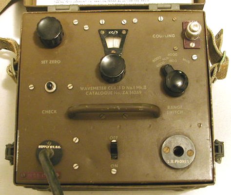
Front view of Wave Meter with the headphones unplugged.
|
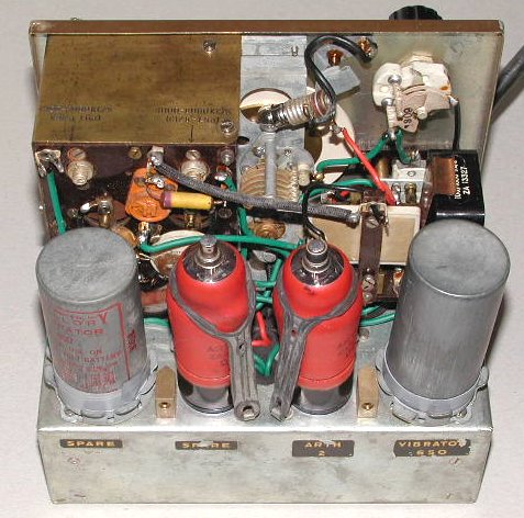
There are a complete set of spares within the Wave Meter. |
||||||||||||||||||||||||||||||||||||||||||||||||||||||||||||
|
All packed up for carrying. |
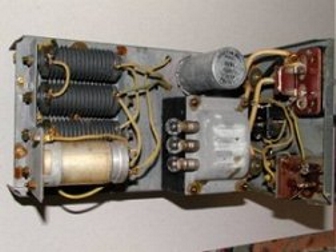
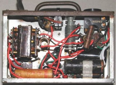
This photo shows the HT power supply on the underside of the chassis.
|
||||||||||||||||||||||||||||||||||||||||||||||||||||||||||||
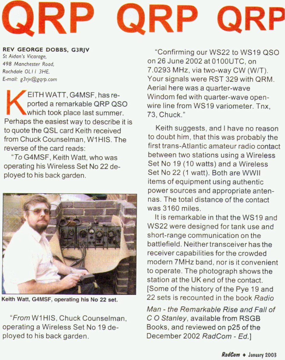
Click HERE to see the article published about the longest distance contact ever
recorded using a Wireless Set No.22 to a Wireless Set No.19. |
|||||||||||||||||||||||||||||||||||||||||||||||||||||||||||||
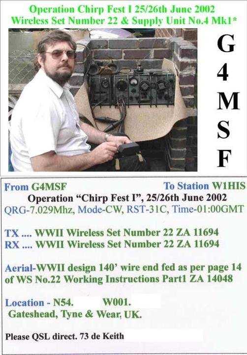
Click HERE to see the QSL card sent for ths contact to W1HIS |
|||||||||||||||||||||||||||||||||||||||||||||||||||||||||||||
All photos and text are copyright ©
2024 Keith Watt RGN(Rtd.)
You may NOT use any content of these pages without my written permission!