Aerial Coupling Equipment F for the Wireless Set No 12
The "12 set" will be a favourite of all those who encountered it in the Cadet Force - and the lucky few who own one now.
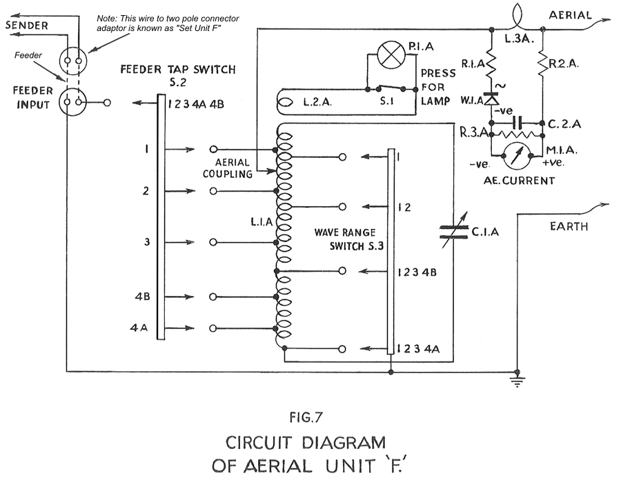
On its own, the WS12 can match an aerial with an impedance of between 100 and 600 ohms, directly connected to the set. There was often a requirement to feed a remote wire aerial and for this reason the Aerial Coupling Equipment F was issued as part of the complete station. This equipment consists of a small adaptor carrying two wires terminated in spades and a two pole Niphan plug, one or two 50ft lengths of feeder and a coupling unit to which the aerial is connected, as shown in the cuircuit below.
The adaptor is known as the Set Unit F, the 50ft feeders as Connectors, Twin No. 56 and the coupling unit as Aerial Unit F. The Aerial Unit appears on the surplus market occasionally but the other two items are rare. Note that the Aerial Couping Equipment is described in Wireless for the Warrior Volume 1 page WS12-7 but there is a source of confusion there. Figure 12-9 is the same diagram as that shown below (it comes from a label pasted inside the unit's lid, or from the working instructions) but is labelled as the Set Unit F. As I have indicated below, the diagram actually shows the whole system, including the Set Unit F, the feeder (Connectors, Twin No. 56) and the Aerial Unit F, the latter occupying most of the diagram, of course. I have indicated the Set Unit and the feeder in italics on the diagram below.
The method of tuning the unit involves first setting up the WS12 into the 100 ohm dummy load supplied with the set. When that has been done, the Set Unit, feeder, Aerial Unit and aerial are substituted and tuning proceeds as indicated by the working instructions reproduced below:
ABRIDGED WORKING INSTRUCTIONS
1. Preliminary
(1) Connect aerial downlead to AERIAL terminal and place unit so that downlead is taut. Connect EARTH terminal to earth pin and knock this into ground
(2) Connect feeder cable (Connector, Twin No. 56) from sender to FEEDER INPUT adaptor and tighten locking ring.
(3) FEEDER TAP and WAVE RANGE SWITCH to same settings as P.A. RANGE on sender (4B for Range 4). AERIAL TUNING control to 180°. AERIAL COUPLING to 12.8 for Range 1, 9.8 for Range 2, zero otherwise.
2. Tuning and Loading
(1) With sender correctly adjusted, rotate AERIAL TUNING control for maximum lamp brilliance. Press button if necessary.
(2) Rotate AERIAL COUPLING control clockwise and re-adjust AERIAL TUNING control progressively for maximum meter reading.
(3) On Range 4, FEEDER TAP and WAVE RANGE SWITCH to 4B if aerial impedance too high to load at 4B and proceed again as above.
With thanks to Barrie Tipper G3WWL and Mike Buckley M1CCF.
Alister Mitchell GM3UDL